Configure a Basic WLAN on the WLC
Summary
This topic configure a WLC WLAN to use the management interface and WPA2 PSK authentication. Start learning CCNA 200-301 for free right now!!
Table of Contents
Video – Configure a Basic WLAN on the WLC
In the previous topic you learned about remote site WLAN configuration. This topic is about configuring a basic WLAN on the WLC.
Click Play in the figure to view a demonstration of configuring a Cisco 3504 WLC with basic WLAN connectivity.
WLC Topology
The topology and addressing scheme used for the videos and this topic are shown in the figure and the table. The access point (AP) is a controller-based AP as opposed to an autonomous AP. Recall that controller-based APs require no initial configuration and are often called lightweight APs (LAPs). LAPs use the Lightweight Access Point Protocol (LWAPP) to communicate with a WLAN controller (WLC). Controller-based APs are useful in situations where many APs are required in the network. As more APs are added, each AP is automatically configured and managed by the WLC.
The figure shows a wireless LAN controller (WLC) topology. PC-A is a RADIUS/SNMP Server connected to R1 on R1s F0/0 interface. PC-B is connected to S1 on S1s F0/6 port. R1 and S1 are connected together on R1s F0/1 interface and on S1s F0/5 interface. S1 is connected to a WLC on its F0/18 port. On S1s F0/1 port its connected to an access point, AP1. A laptop is wirelessly connected to AP1.
Topology

Addressing Table
| Device | Interface | IP Address | Subnet Mask |
|---|---|---|---|
| R1 | F0/0 | 172.16.1.1 | 255.255.255.0 |
| R1 | F0/1.1 | 192.168.200.1 | 255.255.255.0 |
| S1 | VLAN 1 | DHCP | |
| WLC | Management | 192.168.200.254 | 255.255.255.0 |
| AP1 | Wired 0 | 192.168.200.3 | 255.255.255.0 |
| PC-A | NIC | 172.16.1.254 | 255.255.255.0 |
| PC-B | NIC | DHCP | |
| Wireless Laptop | NIC | DHCP | |
Log in to the WLC
Configuring a wireless LAN controller (WLC) is not that much different from configuring a wireless router. The big difference is that a WLC controls APs and provides more services and management capabilities, many of which are beyond the scope of this module.
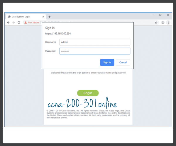
The figure shows the user logging into the WLC with credentials that were configured during initial setup.
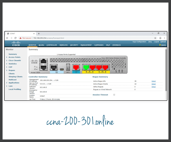
The Network Summary page is a dashboard that provides a quick overview of the number of configured wireless networks, associated access points (APs), and active clients. You can also see the number of rogue access points and clients, as shown in the figure.

View AP Information
Click Access Points from the left menu to view an overall picture of the AP’s system information and performance, as shown in the next figure. The AP is using IP address 192.168.200.3. Because Cisco Discovery Protocol (CDP) is active on this network, the WLC knows that the AP is connected to the FastEthernet 0/1 port on the switch.
This AP in the topology is a Cisco Aironet 1815i which means you can use the command-line and a limited set of familiar IOS commands. In the example, the network administrator pinged the default gateway, pinged the WLC, and verified the wired interface.
AP1# ping 192.168.200.1
Sending 5, 100-byte ICMP Echos to 192.168.200.1, timeout is 2 seconds
!!!!!
Success rate is 100 percent (5/5), round-trip min/avg/max = 1069812.242/1071814.785/1073817.215 ms
AP1# ping 192.168.200.254
Sending 5, 100-byte ICMP Echos to 192.168.200.254, timeout is 2 seconds
!!!!!
Success rate is 100 percent (5/5), round-trip min/avg/max = 1055820.953/1057820.738/1059819.928 ms
AP1# show interface wired 0
wired0    Link encap:Ethernet  HWaddr 2C:4F:52:60:37:E8
          inet addr:192.168.200.3  Bcast:192.168.200.255  Mask:255.255.255.255
          UP BROADCAST RUNNING PROMISC MULTICAST  MTU:1500  Metric:1
          RX packets:2478 errors:0 dropped:3 overruns:0 frame:0
          TX packets:1494 errors:0 dropped:0 overruns:0 carrier:0
          collisions:0 txqueuelen:80
          RX bytes:207632 (202.7 KiB)  TX bytes:300872 (293.8 KiB)
AP1#
Advanced Settings
Most WLC will come with some basic settings and menus that users can quickly access to implement a variety of common configurations. However, as a network administrator, you will typically access the advanced settings. For the Cisco 3504 Wireless Controller, click Advanced in the upper right-hand corner to access the advanced Summary page, as shown in the figure. From here, you can access all the features of the WLC.
Configure a WLAN
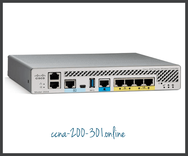
Wireless LAN Controllers have ports and interfaces. Ports are the sockets for the physical connections to the wired network. They resemble switch ports. Interfaces are virtual. They are created in software and are very similar to VLAN interfaces. In fact, each interface that will carry traffic from a WLAN is configured on the WLC as a different VLAN. The Cisco 3504 WLC can support 150 access points and 4096 VLANs, however it only has five physical ports, as shown in the figure. This means that each physical port can support many APs and WLANs. The ports on the WLC are essentially trunk ports that can carry traffic from multiple VLANs to a switch for distribution to multiple APs. Each AP can support multiple WLANs.
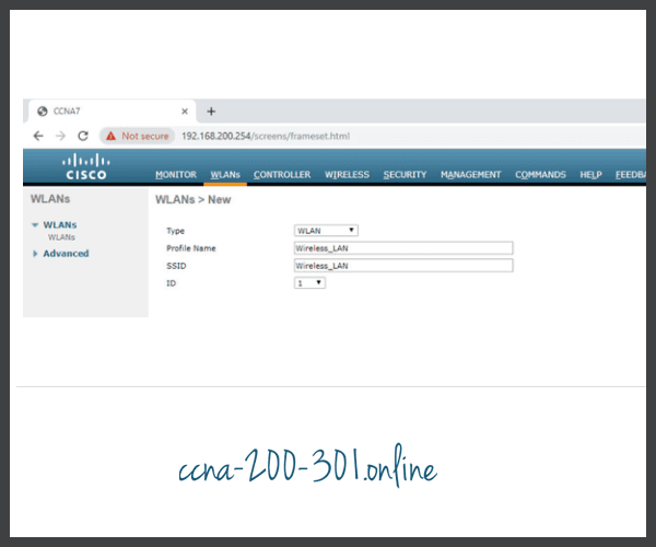
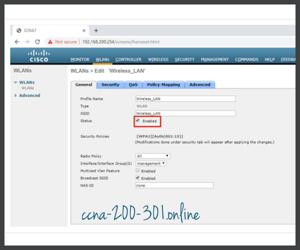
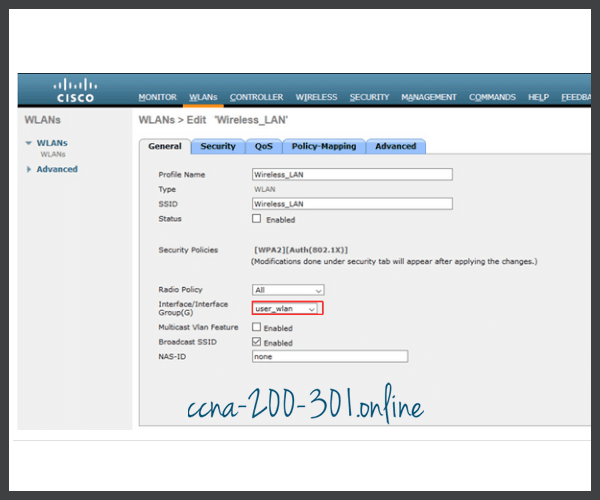
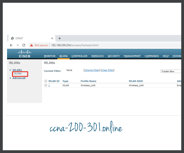
Basic WLAN configuration on the WLC includes the following steps:
- Create the WLAN
- Apply and Enable the WLAN
- Select the Interface
- Secure the WLAN
- Verify the WLAN is Operational
- Monitor the WLAN
- View Wireless Client Information
Click each step for more information and an example GUI.
Packet Tracer – Configure a Basic WLAN on the WLC
In this lab, you will explore some of the features of a wireless LAN controller. You will create a new WLAN on the controller and implement security on that LAN. Then you will configure a wireless host to connect to the new WLAN through an AP that is under the control of the WLC. Finally, you will verify connectivity.
Ready to go! Keep visiting our networking course blog, give Like to our fanpage; and you will find more tools and concepts that will make you a networking professional.


