fbpx
Configure a WPA2 Enterprise WLAN WLC

Configure a WPA2 Enterprise WLAN on the WLC

Configure a WPA2 Enterprise WLAN on the WLC
5

Summary

This topic configure a WLC WLAN to use a VLAN interface, a DHCP server, and WPA2 Enterprise authentication. Start learning CCNA 200-301 for free right now!!

Note: Welcome: This topic is part of Module 13 of the Cisco CCNA 2 course, for a better follow up of the course you can go to the CCNA 2 section to guide you through an order.

Video – Define an SNMP and RADIUS Server on the WLC

The previous topic covered configuring a basic WLAN on the WLC. Now you will learn about configuring a WPA2 Enterprise WLAN.

Click Play in the figure to view a demonstration of configuring SNMP and RADIUS services on the WLC.

SNMP and RADIUS

In the figure, PC-A is running Simple Network Management Protocol (SNMP) and Remote Authentication Dial-In User Service (RADIUS) server software. SNMP is used to monitor the network. The network administrator wants the WLC to forward all SNMP log messages, called traps, to the SNMP server.

In addition, for WLAN user authentication, the network administrator wants to use a RADIUS server for authentication, authorization, and accounting (AAA) services. Instead of entering a publicly known pre-shared key to authenticate, as they do with WPA2-PSK, users will enter their own username and password credentials. The credentials will be verified by the RADIUS server. This way, individual user access can be tracked and audited if necessary and user accounts can be added or modified from a central location. The RADIUS server is required for WLANs that are using WPA2 Enterprise authentication.

Note: SNMP server and RADIUS server configuration is beyond the scope of this module.

The figure depicts a network topology. PC-A is a RADIUS/SNMP Server connected to R1 on R1s F0/0 interface. PC-B is connected to S1 on S1s F0/6 port. R1 and S1 are connected together on R1s F0/1 interface and on S1s F0/5 interface. S1 is connected to a WLC on its F0/18 port. On S1s F0/1 port its connected to an access point, AP1. A laptop is wirelessly connected to AP1.

Topology
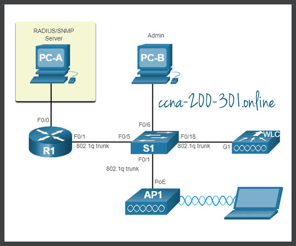
SNMP and RADIUS
SNMP and RADIUS

Configure SNMP Server Information

Click the MANAGEMENT tab to access a variety of management features. SNMP is listed at the top of the menu on the left. Click SNMP to expand the sub-menus, and then click Trap Receivers. Click New… to configure a new SNMP trap receiver, as shown in the figure.
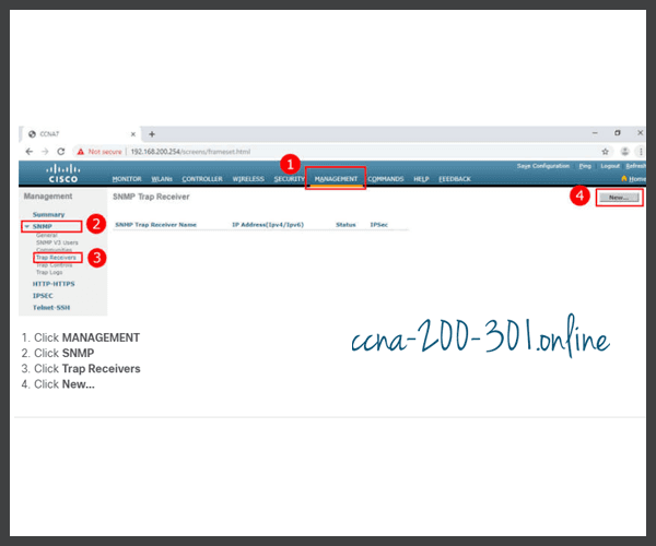
MANAGEMENT SNMP Server

Enter the SNMP Community name and the IP address (IPv4 or IPv6) for the SNMP server. Click Apply. The WLC will now forward SNMP log messages to the SNMP server.

SNMP Community
SNMP Community

Configure RADIUS Server Information

In our example configuration, the network administrator wants to configure a WLAN using WPA2 Enterprise, as opposed to WPA2 Personal or WPA2 PSK. Authentication will be handled by the RADIUS server running on PC-A.

To configure the WLC with the RADIUS server information, click the SECURITY tab > RADIUS > Authentication. No RADIUS servers are currently configured. Click New… to add PC-A as the RADIUS server.
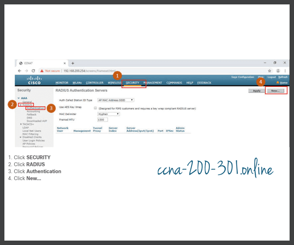
RADIUS Server Information

Enter the IPv4 address for PC-A and the shared secret. This is the password used between the WLC and the RADIUS server. It is not for users. Click Apply, as shown in the figure.

Configure RADIUS Server

After clicking Apply, the list of configured RADIUS Authentication Servers refreshes with the new server listed, as shown in the figure.

RADIUS Authentication Servers

Video – Configure a VLAN for a New WLAN

Click Play in the figure to view a demonstration of configuring a VLAN on the WLC.

Topology with VLAN 5 Addressing

Each WLAN configured on the WLC needs its own virtual interface. The WLC has five physical ports for data traffic. Each physical port can be configured to support multiple WLANs, each on its own virtual interface. Physical ports can also be aggregated to create high-bandwidth links.

The network administrator has decided that the new WLAN will use interface VLAN 5 and network 192.168.5.0/24. R1 already has a subinterface configured and active for VLAN 5, as shown in the topology and show ip interface brief output.

Topology

Topology VLAN 5 Addressing
R1# show ip interface brief
Interface                  IP-Address      OK? Method Status                Protocol
FastEthernet0/0            172.16.1.1      YES manual up                    up
FastEthernet0/1            unassigned      YES unset  up                    up
FastEthernet0/1.1          192.168.200.1   YES manual up                    up
FastEthernet0/1.5          192.168.5.254   YES manual up                    up
(output omitted)
R1#

Configure a New Interface

VLAN interface configuration on the WLC includes the following steps:

  1. Create a new interface.
  2. Configure the VLAN name and ID.
  3. Configure the port and interface address.
  4. Configure the DHCP server address.
  5. Apply and Confirm.
  6. Verify Interfaces.

Click each step for more information and an example GUI.

1. Create a new interface.

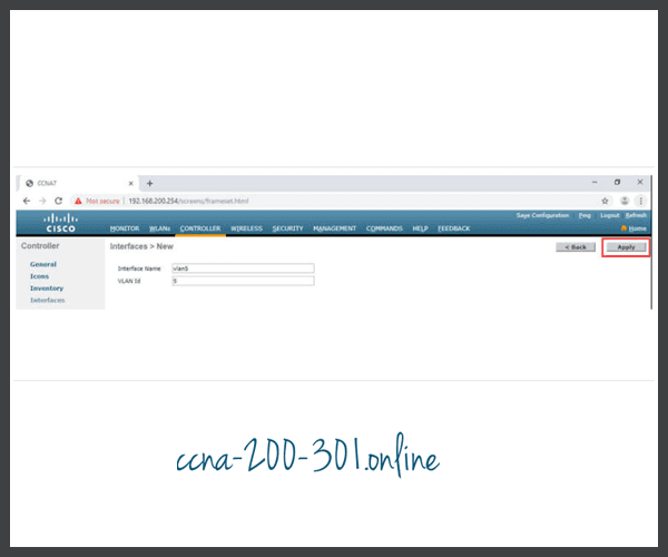
To add a new interface, click CONTROLLER > Interfaces > New..., as shown in the figure.

Create a new interface

2. Configure the VLAN name and ID.

In the figure, the network administrator configures the interface name as vlan5 and the VLAN ID as 5. Clicking Apply will create the new interface.

Configure VLAN name and ID

3. Configure the port and interface address.

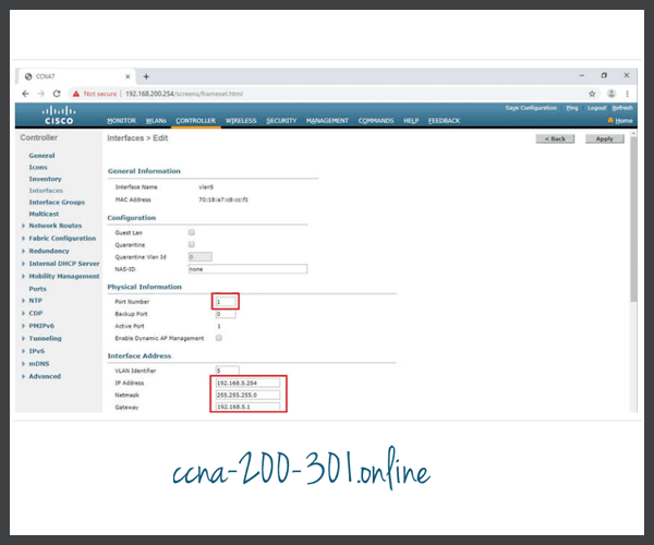
On the Edit page for the interface, configure the physical port number. G1 in the topology is Port Number 1 on the WLC. Then configure the VLAN 5 interface addressing. In the figure, VLAN 5 is assigned IPv4 address 192.168.5.254/24. R1 is the default gateway at IPv4 address 192.168.5.1.

Configure port and interface address

4. Configure the DHCP server address.

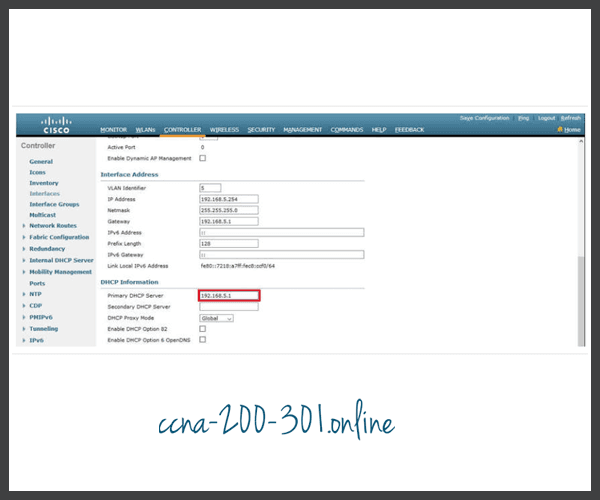
In larger enterprises, WLCs will be configured to forward DHCP messages to a dedicated DHCP server. Scroll down the page to configure the primary DHCP server as IPv4 address 192.168.5.1, as shown in the figure. This is the default gateway router address. The router is configured with a DHCP pool for the WLAN network. As hosts join the WLAN that is associated with the VLAN 5 interface, they will receive addressing information from this pool.

Configure DHCP server address

5. Apply and Confirm.

Scroll to the top and click Apply, as shown in the figure. Click OK for the warning message.

Apply and Confirm
Apply and Confirm

6. Verify Interfaces.

Click Interfaces. The new vlan5 interface is now shown in the list of interfaces with its IPv4 address, as shown in the figure.

Verify Interfaces
Verify Interfaces

Video – Configure a DHCP Scope

Click Play in the figure to view a demonstration of configuring DHCP services.

Configure a DHCP Scope

DHCP scope configuration includes the following steps:

  1. Create a new DHCP scope.
  2. Name the DHCP scope.
  3. Verify the new DHCP scope.
  4. Configure and enable the new DHCP scope.
  5. Verify the enable DHCP scope

Click each step for more information and an example GUI.

1. Create a new DHCP scope.

A DHCP scope is very similar to a DHCP pool on a router. It can include a variety of information including a pool of addresses to assign to DHCP clients, DNS server information, lease times, and more. To configure a new DHCP scope, click Internal DHCP Server > DHCP Scope > New..., as shown in the figure.

Create a new DHCP scope

2. Name the DHCP scope.

On the next screen, name the scope. Because this scope will apply to the wireless management network, the network administrator uses Wireless_Management as the Scope Name and clicks Apply.

Name the DHCP scope
Name the DHCP scope

3. Verify the new DHCP scope.

You are returned to the DHCP Scopes page and can verify the scope is ready to be configured. Click the new Scope Name to configure the DHCP scope.

Verify new DHCP scope

4. Configure and enable the new DHCP scope.

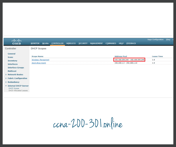
On the Edit screen for the Wireless_Management scope, configure a pool of addresses for the 192.168.200.0/24 network starting at .240 and ending at .249. The network address and subnet mask are configured. The default router IPv4 address is configured, which is the subinterface for R1 at 192.168.200.1. For this example, the rest of the scope is left unchanged. The network administrator selects Enabled from the Status drop down and clicks Apply.

Configure and enable new DHCP scope

5. Verify the enable DHCP scope

The network administrator is returned to the DHCP Scopes page and can verify the scope is ready to be allocated to a new WLAN.

Verify enable DHCP scope

Video – Configure a WPA2 Enterprise WLAN

Click Play in the figure to view a demonstration of configuring a new WLAN with WPA2 Enterprise on the WLC.

Configure a WPA2 Enterprise WLAN

By default, all newly created WLANs on the WLC will use WPA2 with Advanced Encryption System (AES). 802.1X is the default key management protocol used to communicate with the RADIUS server. Because the network administrator already configured the WLC with the IPv4 address of the RADIUS server running on PC-A, the only configuration left to do is to create a new WLAN to use interface vlan5.

Configuring a new WLAN on the WLC includes the following steps:

  1. Create a new WLAN.
  2. Configure the WLAN name and SSID.
  3. Enable the WLAN for VLAN 5.
  4. Verify AES and 802.1X defaults.
  5. Configure WLAN security to use the RADIUS server.
  6. Verify the new WLAN is available.

Click each step for more information and an example GUI.

1. Create a new WLAN.

Click the WLANs tab and then Go to create a new WLAN, as shown in the figure.

Create a new WLAN
Create a new WLAN

2. Configure the WLAN name and SSID.

Fill in the profile name and SSID. In order to be consistent with the VLAN that was previously configured, choose an ID of 5. However, any available value can be used. Click Apply to create the new WLAN, as shown in the figure.

Configure the WLAN name and SSID

3. Enable the WLAN for VLAN 5.

The WLAN is created but it still needs to be enabled and associated with the correct VLAN interface. Change the status to Enabled and choose vlan5 from the Interface/Interface Group(G) dropdown list. Click Apply and click OK to accept the popup message, as shown in the figure.

Enable WLAN for VLAN 5.

4. Verify AES and 802.1X defaults.

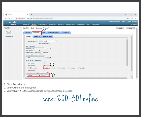
Click the Security tab to view the default security configuration for the new WLAN. The WLAN will use WPA2 security with AES encryption. Authentication traffic is handled by 802.1X between the WLC and the RADIUS server.

Verify AES and 802.1X defaults

5. Configure the RADIUS server.

We now need to select the RADIUS server that will be used to authenticate users for this WLAN. Click the AAA Servers tab. In the dropdown box select the RADIUS server that was configured on the WLC previously. Apply your changes.

Configure RADIUS server

6. Verify that the new WLAN is available.

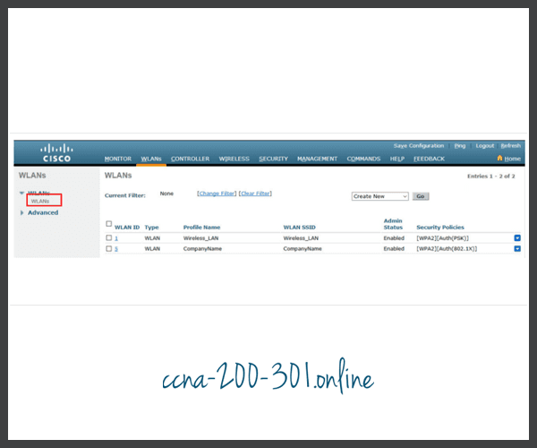
To verify the new WLAN is listed and enabled, click Back or the WLANs submenu on the left. Both the Wireless_LAN WLAN and the CompanyName WLAN are listed. In the figure, notice that both are enabled. Wireless_LAN is using WPA2 with PSK authentication. CompanyName is using WPA2 security with 802.1X authentication.

Verify the new WLAN is available

Packet Tracer – Configure a WPA2 Enterprise WLAN on the WLC

In this activity, you will configure a new WLAN on a wireless LAN controller (WLC), including the VLAN interface that it will use. You will configure the WLAN to use a RADIUS server and WPA2-Enterprise to authenticate users. You will also configure the WLC to use an SNMP server.

Glossary: If you have doubts about any special term, you can consult this computer network dictionary.

Ready to go! Keep visiting our networking course blog, give Like to our fanpage; and you will find more tools and concepts that will make you a networking professional.

Full Network BundleCourse Offer