QoS Implementation Techniques
Summary
This topic explain how QoS uses mechanisms to ensure transmission quality. Start learning CCNA 200-301 for free right now!!
Video Tutorial – QoS Implementation Techniques
Click Play for an overview of classification, marking, trust boundaries, congestion avoidance, shaping and policing.
Avoiding Packet Loss
Now that you have learned about traffic characteristics, queuing algorithms, and QoS models, it is time to learn about QoS implementation techniques.
Let’s start with packet loss. Packet loss is usually the result of congestion on an interface. Most applications that use TCP experience slowdown because TCP automatically adjusts to network congestion. Dropped TCP segments cause TCP sessions to reduce their window sizes. Some applications do not use TCP and cannot handle drops (fragile flows).
The following approaches can prevent drops in sensitive applications:
- Increase link capacity to ease or prevent congestion.
- Guarantee enough bandwidth and increase buffer space to accommodate bursts of traffic from fragile flows. WFQ, CBWFQ, and LLQ can guarantee bandwidth and provide prioritized forwarding to drop-sensitive applications.
- Drop lower-priority packets before congestion occurs. Cisco IOS QoS provides queuing mechanisms, such as weighted random early detection (WRED), that start dropping lower-priority packets before congestion occurs.
QoS Tools
There are three categories of QoS tools, as described in the table:
- Classification and marking tools
- Congestion avoidance tools
- Congestion management tools
Tools for Implementing QoS
| QoS Tools | Description |
|---|---|
| Classification and marking tools |
|
| Congestion avoidance tools |
|
| Congestion management tools |
|
Refer to the figure to help understand the sequence of how these tools are used when QoS is applied to packet flows.
QoS Sequence

As shown in the figure, ingress packets (gray squares) are classified and their respective IP header is marked (colored squares). To avoid congestion, packets are then allocated resources based on defined policies. Packets are then queued and forwarded out the egress interface based on their defined QoS shaping and policing policy.
Classification and Marking
Before a packet can have a QoS policy applied to it, the packet has to be classified. Classification and marking allows us to identify or “mark” types of packets. Classification determines the class of traffic to which packets or frames belong. Only after traffic is marked can policies be applied to it.
How a packet is classified depends on the QoS implementation. Methods of classifying traffic flows at Layer 2 and 3 include using interfaces, ACLs, and class maps. Traffic can also be classified at Layers 4 to 7 using Network Based Application Recognition (NBAR).
Marking means that we are adding a value to the packet header. Devices receiving the packet look at the marked field to see if it matches a defined policy. Marking should be done as close to the source device as possible. This establishes the trust boundary.
How traffic is marked usually depends on the technology. The table in the figure describes some the marking fields used in various technologies. The decision of whether to mark traffic at Layers 2 or 3 (or both) is not trivial and should be made after consideration of the following points:
- Layer 2 marking of frames can be performed for non-IP traffic.
- Layer 2 marking of frames is the only QoS option available for switches that are not “IP aware”.
- Layer 3 marking will carry the QoS information end-to-end.
Traffic Marking for QoS
| QoS Tools | Layer | Marking Field | Width in Bits |
|---|---|---|---|
| Ethernet (802.1Q, 802.1p) | 2 | Class of Service (CoS) | 3 |
| 802.11 (Wi-Fi) | 2 | Wi-Fi Traffic Identifier (TID) | 3 |
| MPLS | 2 | Experimental (EXP) | 3 |
| IPv4 and IPv6 | 3 | IP Precedence (IPP) | 3 |
| IPv4 and IPv6 | 3 | Differentiated Services Code Point (DSCP) | 6 |
Marking at Layer 2
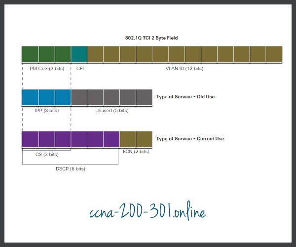
802.1Q is the IEEE standard that supports VLAN tagging at Layer 2 on Ethernet networks. When 802.1Q is implemented, two fields are added to the Ethernet Frame. As shown in the figure, these two fields are inserted into the Ethernet frame following the source MAC address field.
Ethernet Class of Service (CoS) Values
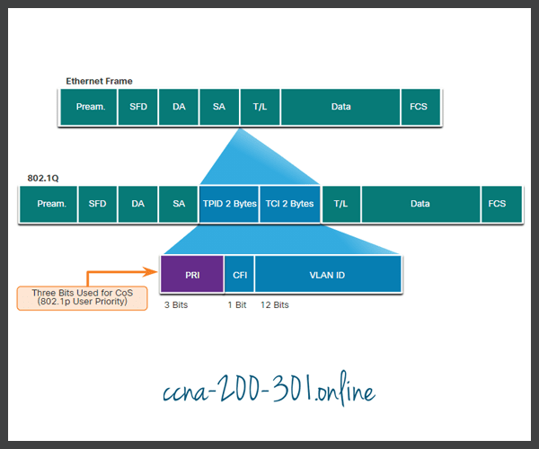
The 802.1Q standard also includes the QoS prioritization scheme known as IEEE 802.1p. The 802.1p standard uses the first three bits in the Tag Control Information (TCI) field. Known as the Priority (PRI) field, this 3-bit field identifies the Class of Service (CoS) markings. Three bits means that a Layer 2 Ethernet frame can be marked with one of eight levels of priority (values 0-7) as displayed in the figure.
Ethernet Class of Service (CoS) Values
| CoS Value | CoS Binary Value | Description |
|---|---|---|
| 0 | 000 | Best-Effort Data |
| 1 | 001 | Medium-Priority Data |
| 2 | 010 | High-Priority Data |
| 3 | 011 | Call Signaling |
| 4 | 100 | Videoconferencing |
| 5 | 101 | Voice bearer (voice traffic) |
| 6 | 110 | Reserved |
| 7 | 111 | Reserved |
Marking at Layer 3
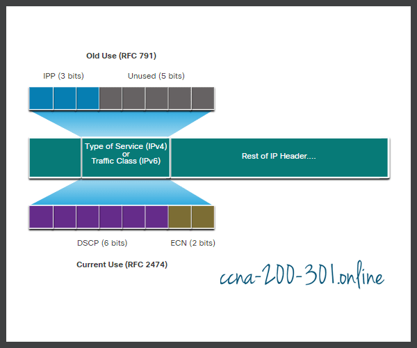
IPv4 and IPv6 specify an 8-bit field in their packet headers to mark packets. As shown in the figure, both IPv4 and IPv6 support an 8-bit field for marking: the Type of Service (ToS) field for IPv4 and the Traffic Class field for IPv6.
IPv4 and IPv6 Packet Headers

Type of Service and Traffic Class Field
The Type of Service (IPv4) and Traffic Class (IPv6) carry the packet marking as assigned by the QoS classification tools. The field is then referred to by receiving devices which forward the packets based on the appropriate assigned QoS policy.
The figure displays the contents of the 8-bit field. In RFC 791, the original IP standard specified the IP Precedence (IPP) field to be used for QoS markings. However, in practice, these three bits did not provide enough granularity to implement QoS.
RFC 2474 supersedes RFC 791 and redefines the ToS field by renaming and extending the IPP field. The new field, as shown in the figure, has 6-bits allocated for QoS. Called the Differentiated Services Code Point (DSCP) field, these six bits offer a maximum of 64 possible classes of service. The remaining two IP Explicit Congestion Notification (ECN) bits can be used by ECN-aware routers to mark packets instead of dropping them. The ECN marking informs downstream routers that there is congestion in the packet flow.
DSCP Values
The 64 DSCP values are organized into three categories:
- Best-Effort (BE) – This is the default for all IP packets. The DSCP value is 0. The per-hop behavior is normal routing. When a router experiences congestion, these packets will be dropped. No QoS plan is implemented.
- Expedited Forwarding (EF) – RFC 3246 defines EF as the DSCP decimal value 46 (binary 101110). The first 3 bits (101) map directly to the Layer 2 CoS value 5 used for voice traffic. At Layer 3, Cisco recommends that EF only be used to mark voice packets.
- Assured Forwarding (AF) – RFC 2597 defines AF to use the 5 most significant DSCP bits to indicate queues and drop preference. The definition of AF is illustrated in the figure.
Assured Forwarding Values
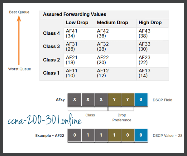
The AFxy formula is specified as follows:
- The first 3 most significant bits are used to designate the class. Class 4 is the best queue and Class 1 is the worst queue.
- The 4th and 5th most significant bits are used to designate the drop preference.
- The 6th most significant bit is set to zero.
For example, AF32 belongs to class 3 (binary 011) and has a medium drop preference (binary 10). The full DSCP value is 28 because you include the 6th 0 bit (binary 011100).
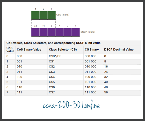
Class Selector Bits
Because the first 3 most significant bits of the DSCP field indicate the class, these bits are also called the Class Selector (CS) bits. These 3 bits map directly to the 3 bits of the CoS field and the IPP field to maintain compatibility with 802.1p and RFC 791, as shown in the figure.
Layer 2 CoS and Layer 3 ToS
The table in the figure shows how the CoS values map to the Class Selectors and the corresponding DSCP 6-bit value. This same table can be used to map IPP values to the Class Selectors.
Mapping CoS to Class Selectors in DSCP
Trust Boundaries
Where should markings occur? Traffic should be classified and marked as close to its source as technically and administratively feasible. This defines the trust boundary, as shown in the figure.
- Trusted endpoints have the capabilities and intelligence to mark application traffic to the appropriate Layer 2 CoS and/or Layer 3 DSCP values. Examples of trusted endpoints include IP phones, wireless access points, videoconferencing gateways and systems, IP conferencing stations, and more.
- Secure endpoints can have traffic marked at the Layer 2 switch.
- Traffic can also be marked at Layer 3 switches / routers.
Re-marking traffic, for example, re-marking CoS values to IP Precedent or DSCP values, is typically necessary.
Various Trust Boundaries

Congestion Avoidance
Congestion management includes queuing and scheduling methods where excess traffic is buffered or queued (and sometimes dropped) while it waits to be sent out an egress interface. Congestion avoidance tools are simpler. They monitor network traffic loads in an effort to anticipate and avoid congestion at common network and internetwork bottlenecks before congestion becomes a problem. These tools can monitor the average depth of the queue, as represented in the figure. When the queue is below the minimum threshold, there are no drops. As the queue fills up to the maximum threshold, a small percentage of packets are dropped. When the maximum threshold is passed, all packets are dropped.
Congestion Avoidance Mechanisms

Some congestion avoidance techniques provide preferential treatment for which packets will get dropped. For example, Cisco IOS QoS includes weighted random early detection (WRED) as a possible congestion avoidance solution. The WRED algorithm allows for congestion avoidance on network interfaces by providing buffer management and allowing TCP traffic to decrease, or throttle back, before buffers are exhausted. Using WRED helps avoid tail drops and maximizes network use and TCP-based application performance. There is no congestion avoidance for User Datagram Protocol (UDP)-based traffic, such as voice traffic. In case of UDP-based traffic, methods such as queuing and compression techniques help to reduce and even prevent UDP packet loss.
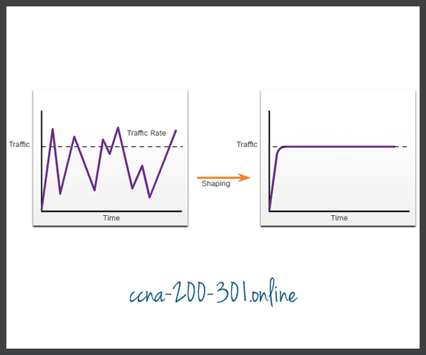
Shaping and Policing
Traffic shaping and traffic policing are two mechanisms provided by Cisco IOS QoS software to prevent congestion.
Traffic shaping retains excess packets in a queue and then schedules the excess for later transmission over increments of time. The result of traffic shaping is a smoothed packet output rate, as shown in the figure.
Shaping Traffic Example
Shaping implies the existence of a queue and of sufficient memory to buffer delayed packets, while policing does not.
Ensure that you have sufficient memory when enabling shaping. In addition, shaping requires a scheduling function for later transmission of any delayed packets. This scheduling function allows you to organize the shaping queue into different queues. Examples of scheduling functions are CBWFQ and LLQ.
Shaping is an outbound concept; packets going out an interface get queued and can be shaped. In contrast, policing is applied to inbound traffic on an interface. When the traffic rate reaches the configured maximum rate, excess traffic is dropped (or remarked).
Policing is commonly implemented by service providers to enforce a contracted customer information rate (CIR). However, the service provider may also allow bursting over the CIR if the service provider’s network is not currently experiencing congestion.
Policing Traffic Example

QoS Policy Guidelines
Your QoS policy must consider the full path from source to destination. If one device in the path is using a different policy than desired, then the entire QoS policy is impacted. For example, the stutter in video playback could be the result of one switch in the path that does not have the CoS value set appropriately.
A few guidelines that help ensure the best experience for end users includes the following:
- Enable queuing at every device in the path between source and destination.
- Classify and mark traffic as close the source as possible.
- Shape and police traffic flows as close to their sources as possible.
Ready to go! Keep visiting our networking course blog, give Like to our fanpage; and you will find more tools and concepts that will make you a networking professional.