Point-to-Point OSPF Networks
Summary
In this topic configure single-area OSPFv2 in a point-to-point network. Start learning CCNA 200-301 for free right now!!
Table of Contents
The network Command Syntax
One type of network classified by OSPF is a point-to-point network. You can specify the interfaces that belong to a point-to-point network by configuring the network command. You can also configure OSPF directly on the interface with the ip ospf command, as we will see later.
Both commands are used to determine which interfaces participate in the routing process for an OSPFv2 area. The basic syntax for the network command is as follows:
Router(config-router)# network network-address wildcard-mask area area-id
- The network-address wildcard-mask syntax is used to enable OSPF on interfaces. Any interfaces on a router that match the network address in the network command are enabled to send and receive OSPF packets.
- The area area-id syntax refers to the OSPF area. When configuring single-area OSPFv2, the network command must be configured with the same area-id value on all routers. Although any area ID can be used, it is good practice to use an area ID of 0 with single-area OSPFv2. This convention makes it easier if the network is later altered to support multiarea OSPFv2.
The Wildcard Mask
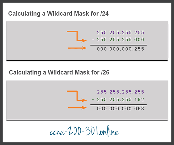
The wildcard mask is typically the inverse of the subnet mask configured on that interface. In a subnet mask, binary 1 is equal to a match and binary 0 is not a match. In a wildcard mask, the reverse is true, as shown in here:
- Wildcard mask bit 0 – Matches the corresponding bit value in the address.
- Wildcard mask bit 1 – Ignores the corresponding bit value in the address.
The easiest method for calculating a wildcard mask is to subtract the network subnet mask from 255.255.255.255, as shown for /24 and /26 subnet masks in the figure.
Check Your Understanding – The Wildcard Masks
Calculate the subnet mask and wildcard mask required to advertise the specified network address in OSPF. Type your answers in the fields provided. Click Check to verify your answers. Click Show Me to see the correct answer.
Click New Problem to continue the activity.
| Network / Subnet / Host | 172.17.2.128/25 |
|---|---|
| Decimal Subnet Mask | |
| Wildcard Mask |
Configure OSPF Using the network Command
Within routing configuration mode, there are two ways to identify the interfaces that will participate in the OSPFv2 routing process. The figure shows the reference topology.
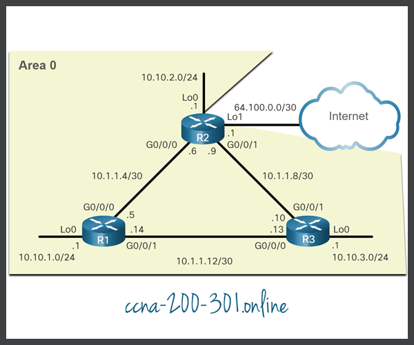
In the first example, the wildcard mask identifies the interface based on the network addresses. Any active interface that is configured with an IPv4 address belonging to that network will participate in the OSPFv2 routing process.
R1(config)# router ospf 10
R1(config-router)# network 10.10.1.0 0.0.0.255 area 0
R1(config-router)# network 10.1.1.4 0.0.0.3 area 0
R1(config-router)# network 10.1.1.12 0.0.0.3 area 0
R1(config-router)#
As an alternative, the second example shows how OSPFv2 can be enabled by specifying the exact interface IPv4 address using a quad zero wildcard mask. Entering network 10.1.1.5 0.0.0.0 area 0 on R1 tells the router to enable interface Gigabit Ethernet 0/0/0 for the routing process. As a result, the OSPFv2 process will advertise the network that is on this interface (10.1.1.4/30).
R1(config)# router ospf 10
R1(config-router)# network 10.10.1.1 0.0.0.0 area 0
R1(config-router)# network 10.1.1.5 0.0.0.0 area 0
R1(config-router)# network 10.1.1.14 0.0.0.0 area 0
R1(config-router)#
The advantage of specifying the interface is that the wildcard mask calculation is not necessary. Notice that in all cases, the area argument specifies area 0.
Syntax Checker – Configure R2 and R3 Using the network Command
Use the Syntax Checker to advertise the networks connected to R2 and R3.
You are currently logged into R2:
- Enter OSPF router configuration mode using process ID 10
- Configure the R2 router ID of 2.2.2.2
R2(config)#router ospf 10
R2(config-router)#router-id 2.2.2.2
R2(config-router)#
Advertise the networks connected to R2 with the appropriate wildcard mask using area 0. Configure the networks in the following order:
- 10.10.2.0/24
- 10.1.1.4/30
- 10.1.1.8/30
R2(config-router)#network 10.10.2.0 0.0.0.255 area 0
R2(config-router)#network 10.1.1.4 0.0.0.3 area 0
R2(config-router)#network 10.1.1.8 0.0.0.3 area 0
R2(config-router)#
\*Mar 25 21:19:21.938: %OSPF-5-ADJCHG: Process 10, Nbr 1.1.1.1 on GigabitEthernet0/0/0 from
LOADING to FULL, Loading Done
You are now configuring R3:
- Enter OSPF router configuration mode using process ID 10
- Configure the R3 router ID.
- Use the network statement to enable OSPF based on the interface address and quad zero wildcard mask for area 0.
- Return to privileged EXEC mode when complete
R3(config)#router ospf 10
R3(config-router)#router-id 3.3.3.3
R3(config-router)#
Use the network statement to enable OSPF based on the interface address and quad zero wildcard mask for area 0. Configure the interfaces in the following order:
- 10.10.3.1
- 10.1.1.10
- 10.1.1.13
R3(config-router)#network 10.10.3.1 0.0.0.0 area 0
R3(config-router)#network 10.1.1.10 0.0.0.0 area 0
R3(config-router)#network 10.1.1.13 0.0.0.0 area 0
R3(config-router)#
\*Mar 26 14:00:55.183: %OSPF-5-ADJCHG: Process 10, Nbr 1.1.1.1 on GigabitEthernet0/0/0 from
LOADING to FULL, Loading Done
\*Mar 26 14:00:55.243: %OSPF-5-ADJCHG: Process 10, Nbr 2.2.2.2 on GigabitEthernet0/0/1 from
LOADING to FULL, Loading Done
R3#
You successfully advertised the OSPF networks on R2 and R3.
Configure OSPF Using the ip ospf Command
You can also configure OSPF directly on the interface instead of using the network command. To configure OSPF directly on the interface, use the ip ospf interface configuration mode command. The syntax is as follows:
Router(config-if)# ip ospf process-id area area-id
For R1, remove the network commandsby using the no form of the network commands. And then go to each interface and configure the ip ospf command, as shown in the command window.
R1(config)# router ospf 10
R1(config-router)# no network 10.10.1.1 0.0.0.0 area 0
R1(config-router)# no network 10.1.1.5 0.0.0.0 area 0
R1(config-router)# no network 10.1.1.14 0.0.0.0 area 0
R1(config-router)# interface GigabitEthernet 0/0/0
R1(config-if)# ip ospf 10 area 0
R1(config-if)# interface GigabitEthernet 0/0/1
R1(config-if)# ip ospf 10 area 0
R1(config-if)# interface Loopback 0
R1(config-if)# ip ospf 10 area 0
R1(config-if)#
Syntax Checker – Configure R2 and R3 Using the ip ospf Command
Use the Syntax Checker to advertise the networks by configuring the interfaces for OSPF on R2 and R3.
You are currently logged into R2. The network commands are already removed. Configure OSPF routing using process ID 10, in area 0, on each interface, in that order. Use the following shortened interface names:
- lo0
- g0/0/0
- g0/0/1
R2(config)#interface lo0
R2(config-if)#ip ospf 10 area 0
R2(config-if)#interface g0/0/0
R2(config-if)#ip ospf 10 area 0
R2(config-if)#interface g0/0/1
R2(config-if)#ip ospf 10 area 0
\*Mar 25 21:19:21.938: %OSPF-5-ADJCHG: Process 10, Nbr 1.1.1.1 on GigabitEthernet0/0/0 from
LOADING to FULL, Loading Done
You are now logged into R3. The network commands are already removed. Configure OSPF routing using process ID 10, in area 0, on each interface, in that order. Use the following shortened interface names:
- lo0
- g0/0/0
- g0/0/1
R3(config)#interface lo0
R2(config-if)#ip ospf 10 area 0
R2(config-if)#interface g0/0/0
R2(config-if)#ip ospf 10 area 0
R2(config-if)#interface g0/0/1
R2(config-if)#ip ospf 10 area 0
\*Mar 26 14:00:55.183: %OSPF-5-ADJCHG: Process 10, Nbr 1.1.1.1 on GigabitEthernet0/0/0 from
LOADING to FULL, Loading Done
\*Mar 26 14:00:55.243: %OSPF-5-ADJCHG: Process 10, Nbr 2.2.2.2 on GigabitEthernet0/0/1 from
LOADING to FULL, Loading Done
R3(config-router)#
You successfully configured the interfaces to advertise the OSPF networks.
Passive Interface
By default, OSPF messages are forwarded out all OSPF-enabled interfaces. However, these messages really only need to be sent out interfaces that are connecting to other OSPF-enabled routers.
Refer to the topology in the figure. OSPFv2 messages are forwarded out the three loopback interfaces even though no OSPFv2 neighbor exists on these simulated LANs. In a production network, these loopbacks would be physical interfaces to networks with users and traffic. Sending out unneeded messages on a LAN affects the network in three ways, as follows:
- Inefficient Use of Bandwidth – Available bandwidth is consumed transporting unnecessary messages.
- Inefficient Use of Resources – All devices on the LAN must process and eventually discard the message.
- Increased Security Risk – Without additional OSPF security configurations, OSPF messages can be intercepted with packet sniffing software. Routing updates can be modified and sent back to the router, corrupting the routing table with false metrics that misdirect traffic.
Configure Passive Interfaces
Use the passive-interface router configuration mode command to prevent the transmission of routing messages through a router interface, but still allow that network to be advertised to other routers. The configuration example identifies the R1 Loopback 0/0/0 interface as passive.
The show ip protocols command is then used to verify that the Loopback 0 interface is listed as passive. The interface is still listed under the heading, “Routing on Interfaces Configured Explicitly (Area 0)”, which means that this network is still included as a route entry in OSPFv2 updates that are sent to R2 and R3.
R1(config)# router ospf 10
R1(config-router)# passive-interface loopback 0
R1(config-router)# end
R1#
*May 23 20:24:39.309: %SYS-5-CONFIG_I: Configured from console by console
R1# show ip protocols
*** IP Routing is NSF aware ***
(output omitted)
Routing Protocol is "ospf 10"
  Outgoing update filter list for all interfaces is not set
  Incoming update filter list for all interfaces is not set
  Router ID 1.1.1.1
  Number of areas in this router is 1. 1 normal 0 stub 0 nssa
  Maximum path: 4
  Routing for Networks:
  Routing on Interfaces Configured Explicitly (Area 0):
    Loopback0
    GigabitEthernet0/0/1
    GigabitEthernet0/0/0
  Passive Interface(s):
    Loopback0
  Routing Information Sources:
    Gateway         Distance      Last Update
    3.3.3.3              110      01:01:48
    2.2.2.2              110      01:01:38
  Distance: (default is 110)
R1#
Syntax Checker – Configure R2 and R3 Passive Interfaces
Use the Syntax Checker to configure the Loopback interfaces on R2 as a passive. As an alternative, all interfaces can be made passive using the passive-interface default command. Interfaces that should not be passive can be re-enabled using the no passive-interface command. Configure R3 with the passive-interface default command and then re-enable the Gigabit Ethernet interfaces.
You are currently logged into R2.
- Enter OSPF router configuration mode using process ID 10.
- Configure the Loopback interface as passive using the shortened interface name lo0.
- Return to privileged EXEC mode.
- Verify the OSPF settings with the show ip protocols command.
R2(config)#router ospf 10
R2(config-router)#passive-interface lo0
R2(config-router)#end
\*May 23 20:27:20.718: %SYS-5-CONFIG\_I: Configured from console by console
R2#show ip protocols
\*\*\* IP Routing is NSF aware \*\*\*
(output omitted)
Routing Protocol is "ospf 10"
  Outgoing update filter list for all interfaces is not set
  Incoming update filter list for all interfaces is not set
  Router ID 2.2.2.2
  Number of areas in this router is 1. 1 normal 0 stub 0 nssa
  Maximum path: 4
  Routing for Networks:
  Routing on Interfaces Configured Explicitly (Area 0):
    Loopback0
    GigabitEthernet0/0/1
    GigabitEthernet0/0/0
  Passive Interface(s):
    Loopback0
  Routing Information Sources:
    Gateway         Distance      Last Update
    3.3.3.3              110      02:07:48
    1.1.1.1              110      02:34:53
  Distance: (default is 110)
R2#
R3(config)#router ospf 10 R3(config-router)#passive-interface default \*Jun 5 23:06:46.668: %OSPF-5-ADJCHG: Process 10, Nbr 1.1.1.1 on GigabitEthernet0/0/0 from FULL to DOWN, Neighbor Down: Interface down or detached \*Jun 5 23:06:46.669: %OSPF-5-ADJCHG: Process 10, Nbr 2.2.2.2 on GigabitEthernet0/0/1 from FULL to DOWN, Neighbor Down: Interface down or detached R3(config-router)#no passive-interface g0/0/0 \*Jun 5 23:07:07.746: %OSPF-5-ADJCHG: Process 10, Nbr 1.1.1.1 on GigabitEthernet0/0/0 from LOADING to FULL, Loading Done R3(config-router)#no passive-interface g0/0/1 \*Jun 5 23:07:17.841: %OSPF-5-ADJCHG: Process 10, Nbr 2.2.2.2 on GigabitEthernet0/0/1 from LOADING to FULL, Loading Done R3(config-router)#end \* Jun 5 23:07:35.732: %SYS-5-CONFIG\_I: Configured from console by console
R3#>show ip protocols
\*\*\* IP Routing is NSF aware \*\*\*
(output omitted)
Routing Protocol is "ospf 10"
  Outgoing update filter list for all interfaces is not set
  Incoming update filter list for all interfaces is not set
  Router ID 3.3.3.3
  Number of areas in this router is 1. 1 normal 0 stub 0 nssa
  Maximum path: 4
  Routing for Networks:
  Routing on Interfaces Configured Explicitly (Area 0):
    Loopback0
    GigabitEthernet0/0/1
    GigabitEthernet0/0/0
  Passive Interface(s):
    Serial0/1/0
    Serial0/1/1
    Loopback0
  Routing Information Sources:
    Gateway         Distance      Last Update
    1.1.1.1              110      00:00:59
    2.2.2.2              110      00:00:48
  Distance: (default is 110)
R3#
You successfully configured passive interfaces for R2 and R3.
OSPF Point-to-Point Networks
By default, Cisco routers elect a DR and BDR on Ethernet interfaces, even if there is only one other device on the link. You can verify this with the show ip ospf interface command, as shown in the example for G0/0/0 of R1.
R1# show ip ospf interface GigabitEthernet 0/0/0
GigabitEthernet0/0/0 is up, line protocol is up
  Internet Address 10.1.1.5/30, Area 0, Attached via Interface Enable
  Process ID 10, Router ID 1.1.1.1, Network Type BROADCAST, Cost: 1
  Topology-MTID    Cost    Disabled    Shutdown      Topology Name
        0           1         no          no            Base
  Enabled by interface config, including secondary ip addresses
  Transmit Delay is 1 sec, State BDR, Priority 1
  Designated Router (ID) 2.2.2.2, Interface address 10.1.1.6
  Backup Designated router (ID) 1.1.1.1, Interface address 10.1.1.5
  Timer intervals configured, Hello 10, Dead 40, Wait 40, Retransmit 5
    oob-resync timeout 40
    Hello due in 00:00:08
  Supports Link-local Signaling (LLS)
  Cisco NSF helper support enabled
  IETF NSF helper support enabled
  Index 1/2/2, flood queue length 0
  Next 0x0(0)/0x0(0)/0x0(0)
  Last flood scan length is 1, maximum is 1
  Last flood scan time is 0 msec, maximum is 0 msec
  Neighbor Count is 1, Adjacent neighbor count is 1
    Adjacent with neighbor 2.2.2.2  (Designated Router)
  Suppress hello for 0 neighbor(s)
R1#
R1 is the BDR and R2 is the DR. The DR/ BDR election process is unnecessary as there can only be two routers on the point-to-point network between R1 and R2. Notice in the output that the router has designated the network type as BROADCAST. To change this to a point-to-point network, use the interface configuration command ip ospf network point-to-point on all interfaces where you want to disable the DR/BDR election process. The example below shows this configuration for R1. The OSPF neighbor adjacency status will go down for a few milliseconds.
R1(config)# interface GigabitEthernet 0/0/0
R1(config-if)# ip ospf network point-to-point
*Jun  6 00:44:05.208: %OSPF-5-ADJCHG: Process 10, Nbr 2.2.2.2 on GigabitEthernet0/0/0 from FULL to DOWN, Neighbor Down: Interface down or detached
*Jun  6 00:44:05.211: %OSPF-5-ADJCHG: Process 10, Nbr 2.2.2.2 on GigabitEthernet0/0/0 from LOADING to FULL, Loading Done
R1(config-if)# interface GigabitEthernet 0/0/1
R1(config-if)# ip ospf network point-to-point
*Jun  6 00:44:45.532: %OSPF-5-ADJCHG: Process 10, Nbr 3.3.3.3 on GigabitEthernet0/0/1 from FULL to DOWN, Neighbor Down: Interface down or detached
*Jun  6 00:44:45.535: %OSPF-5-ADJCHG: Process 10, Nbr 3.3.3.3 on GigabitEthernet0/0/1 from LOADING to FULL, Loading Done
R1(config-if)# end
R1# show ip ospf interface GigabitEthernet 0/0/0
GigabitEthernet0/0/0 is up, line protocol is up
  Internet Address 10.1.1.5/30, Area 0, Attached via Interface Enable
  Process ID 10, Router ID 1.1.1.1, Network Type POINT_TO_POINT, Cost: 1
  Topology-MTID    Cost    Disabled    Shutdown      Topology Name
        0           1         no          no            Base
  Enabled by interface config, including secondary ip addresses
  Transmit Delay is 1 sec, State POINT_TO_POINT
  Timer intervals configured, Hello 10, Dead 40, Wait 40, Retransmit 5
    oob-resync timeout 40
    Hello due in 00:00:04
  Supports Link-local Signaling (LLS)
  Cisco NSF helper support enabled
  IETF NSF helper support enabled
  Index 1/2/2, flood queue length 0
  Next 0x0(0)/0x0(0)/0x0(0)
  Last flood scan length is 1, maximum is 2
  Last flood scan time is 0 msec, maximum is 1 msec
  Neighbor Count is 1, Adjacent neighbor count is 1
    Adjacent with neighbor 2.2.2.2
  Suppress hello for 0 neighbor(s)
R1#
Notice that the Gigabit Ethernet 0/0/0 interface now lists the network type as POINT_TO_POINT and that there is no DR or BDR on the link.
Loopbacks and Point-to-Point Networks
We use loopbacks to provide additional interfaces for a variety of purposes. In this case, we are using loopbacks to simulate more networks than the equipment can support. By default, loopback interfaces are advertised as /32 host routes. For example, R1 would advertise the 10.10.1.0/24 network as 10.10.1.1/32 to R2 and R3.
R2# show ip route | include 10.10.1
O        10.10.1.1/32 [110/2] via 10.1.1.5, 00:03:05, GigabitEthernet0/0/0
To simulate a real LAN, the Loopback 0 interface is configured as a point-to-point network so that R1 will advertise the full 10.10.1.0/24 network to R2 and R3.
R1(config-if)# interface Loopback 0
R1(config-if)# ip ospf network point-to-point
Now R2 receives the more accurate, simulated LAN network address of 10.10.1.0/24.
R2# show ip route | include 10.10.1
O 10.10.1.0/24 [110/2] via 10.1.1.5, 00:00:30, GigabitEthernet0/0/0Packet Tracer – Point-to-Point Single-Area OSPFv2 Configuration
In this Packet Tracer activity, you will configure the single-area OSPFv2 with the following:
- Explicitly configure router IDs.
- Configure the
networkcommand on R1 using wildcard mask based on the subnet mask. - Configure the
networkcommand on R2 using a quad-zero wildcard mask. - Configure the
ip ospf interfacecommand on R3. - Configure passive interfaces.
- Verify OSPF operation using the
show ip protocolsandshow ip routecommands.
Ready to go! Keep visiting our networking course blog, give Like to our fanpage; and you will find more tools and concepts that will make you a networking professional.