PAT
Summary
This topic configure PAT using the CLI. Start learning CCNA 200-301 for free right now!!
Table of Contents
PAT Scenario
In this topic, you will learn how to configure and verify PAT. It includes a Packet Tracer activity to test your skills and knowledge. There are two ways to configure PAT, depending on how the ISP allocates public IPv4 addresses. In the first instance, the ISP allocates a single public IPv4 address that is required for the organization to connect to the ISP and in the other, it allocates more than one public IPv4 address to the organization.
Both methods will be demonstrated using the scenario shown in the figure.
Configure PAT to Use a Single IPv4 Address
To configure PAT to use a single IPv4 address, simply add the keyword overload to the ip nat inside source command. The rest of the configuration is the similar to static and dynamic NAT configuration except that with PAT, multiple hosts can use the same public IPv4 address to access the internet.
In the example, all hosts from network 192.168.0.0/16 (matching ACL 1) that send traffic through router R2 to the internet will be translated to IPv4 address 209.165.200.225 (IPv4 address of interface S0/1/1). The traffic flows will be identified by port numbers in the NAT table because the overload keyword is configured.
R2(config)# ip nat inside source list 1 interface serial 0/1/0 overload
R2(config)# access-list 1 permit 192.168.0.0 0.0.255.255
R2(config)# interface serial0/1/0
R2(config-if)# ip nat inside
R2(config-if)# exit
R2(config)# interface Serial0/1/1
R2(config-if)# ip nat outside
Configure PAT to Use an Address Pool
An ISP may allocate more than one public IPv4 address to an organization. In this scenario the organization can configure PAT to use a pool of IPv4 public addresses for translation.
If a site has been issued more than one public IPv4 address, these addresses can be part of a pool that is used by PAT. The small pool of addresses is shared among a larger number of devices, with multiple hosts using the same public IPv4 address to access the internet. To configure PAT for a dynamic NAT address pool, simply add the keyword overload to the ip nat inside source command.
The topology for this scenario is repeated in the figure for your convenience.

In the example, NAT-POOL2 is bound to an ACL to permit 192.168.0.0/16 to be translated. These hosts can share an IPv4 address from the pool because PAT is enabled with the keyword overload.
R2(config)# ip nat pool NAT-POOL2 209.165.200.226 209.165.200.240 netmask 255.255.255.224
R2(config)# access-list 1 permit 192.168.0.0 0.0.255.255
R2(config)# ip nat inside source list 1 pool NAT-POOL2 overload
R2(config)#
R2(config)# interface serial0/1/0
R2(config-if)# ip nat inside
R2(config-if)# exit
R2(config)# interface serial0/1/1
R2(config-if)# ip nat outside
R2(config-if)# end
R2#
Analyze PAT – PC to Server
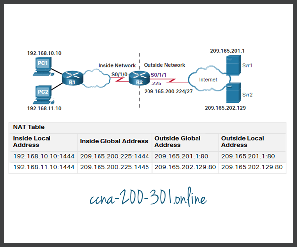
The process of NAT overload is the same whether a pool of addresses is used, or a single address is used. In this figure, PAT is configured to use a single public IPv4 address, instead of a pool of addresses. PC1 wants to communicate with the web server, Svr1. At the same time another client, PC2, wants to establish a similar session with the web server Svr2. Both PC1 and PC2 are configured with private IPv4 addresses, with R2 enabled for PAT.

In the figure, the following steps are shown:
- Both PC1 and PC2 are sending packets to Svr1 and Svr2, respectively. PC1 has the source IPv4 address 192.168.10.10 and is using TCP source port 1444. PC2 has the source IPv4 address 192.168.10.11 and coincidentally uses the same TCP source port of 1444.
- The packet from PC1 reaches R2 first. Using PAT, R2 modifies the source IPv4 address to 209.165.200.225 (inside global address). There are no other devices in the NAT table using port 1444, so PAT maintains the same port number. The packet is then forwarded towards Svr1 at 209.165.201.1.
- Next, the packet from PC2 arrives at R2. PAT is configured to use a single inside global IPv4 address for all translations, 209.165.200.225. Similar to the translation process for PC1, PAT changes the source IPv4 address of PC2 to the inside global address 209.165.200.225. However, PC2 has the same source port number as a current PAT entry, the translation for PC1. PAT increments the source port number until it is a unique value in its table. In this instance, the source port entry in the NAT table and the packet for PC2 receives 1445.
Analyze PAT – Server to PC
Although PC1 and PC2 are using the same translated address, the inside global address of 209.165.200.225, and the same source port number of 1444; the modified port number for PC2 (1445) makes each entry in the NAT table unique. This will become evident with the packets sent from the servers back to the clients, as shown in the figure.

In this second figure, the steps from the servers to the PCs are as follows:
- The servers use the source port from the received packet as the destination port, and the source address as the destination address for the return traffic. The servers seem as if they are communicating with the same host at 209.165.200.225; however, this is not the case.
- As the packets arrive, R2 locates the unique entry in its NAT table using the destination address and the destination port of each packet. In the case of the packet from Svr1, the destination IPv4 address of 209.165.200.225 has multiple entries but only one with the destination port 1444. Using the entry in its table, R2 changes the destination IPv4 address of the packet to 192.168.10.10, with no change required for the destination port. The packet is then forwarded toward PC1.
- When the packet from Svr2 arrives R2 performs a similar translation. The destination IPv4 address of 209.165.200.225 is located, again with multiple entries. However, using the destination port of 1445, R2 is able to uniquely identify the translation entry. The destination IPv4 address is changed to 192.168.10.11. In this case, the destination port must also be modified back to its original value of 1444, which is stored in the NAT table. The packet is then forwarded toward PC2.
Verify PAT
Router R2 has been configured to provide PAT to the 192.168.0.0/16 clients. When the internal hosts exit router R2 to the internet, they are translated to an IPv4 address from the PAT pool with a unique source port number.
The same commands used to verify static and dynamic NAT are used to verify PAT, as shown in the example output. The show ip nat translations command displays the translations from two different hosts to different web servers. Notice that two different inside hosts are allocated the same IPv4 address of 209.165.200.226 (inside global address). The source port numbers in the NAT table differentiate the two transactions.
R2# show ip nat translations
Pro Inside global          Inside local         Outside local      Outside global
tcp 209.165.200.225:1444  192.168.10.10:1444  209.165.201.1:80   209.165.201.1:80
tcp 209.165.200.225:1445  192.168.11.10:1444  209.165.202.129:80 209.165.202.129:80
R2#
In the next example, the show ip nat statistics command verifies that NAT-POOL2 has allocated a single address for both translations. Included in the output is information about the number and type of active translations, NAT configuration parameters, the number of addresses in the pool, and how many have been allocated.
R2# show ip nat statistics
Total active translations: 4 (0 static, 2 dynamic; 2 extended)
Peak translations: 2, occurred 00:31:43 ago
Outside interfaces:
  Serial0/1/1
Inside interfaces:
  Serial0/1/0
Hits: 4  Misses: 0
CEF Translated packets: 47, CEF Punted packets: 0
Expired translations: 0
Dynamic mappings:
-- Inside Source
[Id: 3] access-list 1 pool NAT-POOL2 refcount 2
 pool NAT-POOL2: netmask 255.255.255.224
	start 209.165.200.225 end 209.165.200.240
	type generic, total addresses 15, allocated 1 (6%), misses 0
(output omitted)
R2#
Packet Tracer – Configure PAT
In this Packet Tracer, you will complete the following objectives:
- Part 1: Configure Dynamic NAT with Overload
- Part 2: Verify Dynamic NAT with Overload Implementation
- Part 3: Configure PAT using an Interface
- Part 4: Verify PAT Interface Implementation
Ready to go! Keep visiting our networking course blog, give Like to our fanpage; and you will find more tools and concepts that will make you a networking professional.