


Packet Forwarding
Summary
This topic explain how routers forward packets to the destination. Start learning CCNA 200-301 for free right now!!
Table of Contents
Packet Forwarding Decision Process
Now that the router has determined the best path for a packet based on the longest match, it must determine how to encapsulate the packet and forward it out the correct egress interface.
The figure demonstrates how a router first determines the best path, and then forwards the packet.

The following steps describe the packet forwarding process shown in the figure:
- The data link frame with an encapsulated IP packet arrives on the ingress interface.
- The router examines the destination IP address in the packet header and consults its IP routing table.
- The router finds the longest matching prefix in the routing table.
- The router encapsulates the packet in a data link frame and forwards it out the egress interface. The destination could be a device connected to the network or a next-hop router.
- However, if there is no matching route entry the packet is dropped.
Click each button for a description of the three things a router can do with a packet after it has determined the best path.
End-to-End Packet Forwarding
The primary responsibility of the packet forwarding function is to encapsulate packets in the appropriate data link frame type for the outgoing interface. For example, the data link frame format for a serial link could be Point-to-Point (PPP) protocol, High-Level Data Link Control (HDLC) protocol, or some other Layer 2 protocol.
Click each button and play the animations of PC1 sending a packet to PC2. Notice how the contents and format of the data link frame change at each hop.
- PC1 Sends Packet to PC2
- R1 Forwards the Packet to PC2
- R2 Forwards the Packet to R3
- R3 Forwards the Packet to PC2
In the first animation, PC1 sends a packet to PC2. Note that if an ARP entry does not exist in the ARP table for the default gateway of 192.168.1.1, PC1 sends an ARP request. Router R1 would then return an ARP reply.

R1 now forwards the packet to PC2. Because the exit interface is on an Ethernet network, R1 must resolve the next-hop IPv4 address with a destination MAC address using its ARP table. If an ARP entry does not exist in the ARP table for the next-hop interface of 192.168.2.2, R1 sends an ARP request. R2 would then return an ARP Reply.
R2 now forwards the packet to R3. Because the exit interface is not an Ethernet network, R2 does not have to resolve the next-hop IPv4 address with a destination MAC address. When the interface is a point-to-point (P2P) serial connection, the router encapsulates the IPv4 packet into the proper data link frame format used by the exit interface (HDLC, PPP, etc.). Because there are no MAC addresses on serial interfaces, R2 sets the data link destination address to an equivalent of a broadcast.

R3 now forwards the packet to PC2. Because the destination IPv4 address is on a directly connected Ethernet network, R3 must resolve the destination IPv4 address of the packet with its associated MAC address. If the entry is not in the ARP table, R3 sends an ARP request out of its FastEthernet 0/0 interface. PC2 would then return an ARP reply with its MAC address.
Packet Forwarding Mechanisms
As mentioned previously, the primary responsibility of the packet forwarding function is to encapsulate packets in the appropriate data link frame type for the outgoing interface. The more efficiently a router can perform this task, the faster packets can be forwarded by the router. Routers support the following three packet forwarding mechanisms:
- Process switching
- Fast switching
- Cisco Express Forwarding (CEF)
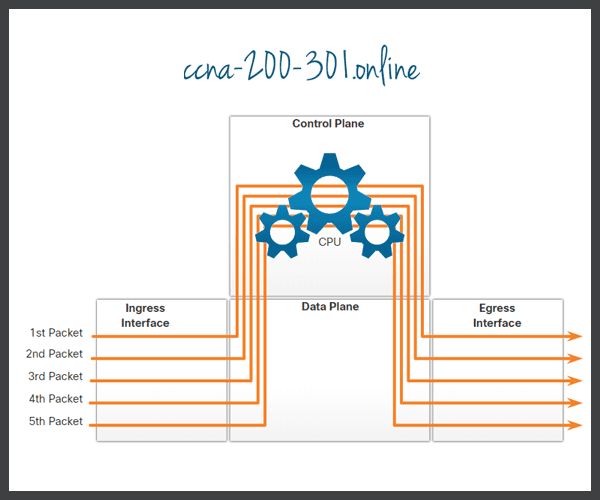
Assume that there is a traffic flow which consists of five packets. They are all going to the same destination. Click each button for more information about the packet forwarding mechanisms.
An older packet forwarding mechanism still available for Cisco routers. When a packet arrives on an interface, it is forwarded to the control plane where the CPU matches the destination address with an entry in its routing table, and then determines the exit interface and forwards the packet. It is important to understand that the router does this for every packet, even if the destination is the same for a stream of packets. This process-switching mechanism is very slow and is rarely implemented in modern networks. Contrast this with fast switching.
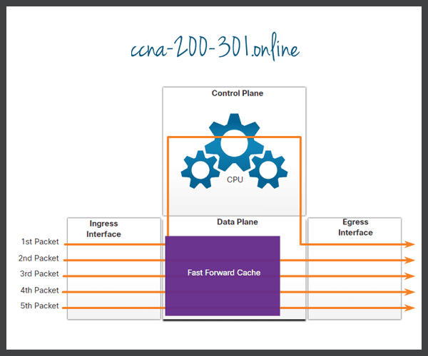
Fast switching is another, older packet forwarding mechanism which was the successor to process switching. Fast switching uses a fast-switching cache to store next-hop information. When a packet arrives on an interface, it is forwarded to the control plane where the CPU searches for a match in the fast-switching cache. If it is not there, it is process-switched and forwarded to the exit interface. The flow information for the packet is also stored in the fast-switching cache. If another packet going to the same destination arrives on an interface, the next-hop information in the cache is re-used without CPU intervention.
With fast switching, notice how only the first packet of a flow is process-switched and added to the fast-switching cache. The next four packets are quickly processed based on the information in the fast-switching cache.
CEF is the most recent and default Cisco IOS packet-forwarding mechanism. Like fast switching, CEF builds a Forwarding Information Base (FIB), and an adjacency table. However, the table entries are not packet-triggered like fast switching but change-triggered, such as when something changes in the network topology. Therefore, when a network has converged, the FIB and adjacency tables contain all the information that a router would have to consider when forwarding a packet. Cisco Express Forwarding is the fastest forwarding mechanism and the default on Cisco routers and multilayer switches.
CEF builds the FIB and adjacency tables after the network has converged. All five packets are quickly processed in the data plane.

A common analogy used to describe these three different packet-forwarding mechanisms is as follows:
- Process switching solves a problem by doing math long hand, even if it is the identical problem that was just solved.
- Fast switching solves a problem by doing math long hand one time and remembering the answer for subsequent identical problems.
- CEF solves every possible problem ahead of time in a spreadsheet.
Ready to go! Keep visiting our networking course blog, give Like to our fanpage; and you will find more tools and concepts that will make you a networking professional.

