WAN Operations
Summary
This topic explain how WANs operate. Start learning CCNA 200-301 for free right now!!
Table of Contents
WAN Standards
Now that you understand how critical WANs are to large networks, this topic discusses how they work. The concept of a WAN has been around for many years. Consider that the telegraph system was the first large-scale WAN, followed by radio, telephone system, television, and now data networks. Many of the technologies and standards developed for these WANs were used as the basis for network WANs.
Modern WAN standards are defined and managed by a number of recognized authorities including the following:
- TIA/EIA – Telecommunications Industry Association and Electronic Industries Alliance
- ISO – International Organization for Standardization
- IEEE – Institute of Electrical and Electronics Engineers
WANs in the OSI Model
Most WAN standards focus on the physical layer (OSI Layer 1) and the data link layer (OSI Layer 2), as shown in the figure.

Layer 1 Protocols
Layer 1 protocols describe the electrical, mechanical, and operational components needed to transmit bits over a WAN. For example, service providers commonly use high-bandwidth optical fiber media to span long distances (i.e., long haul) using the following Layer 1 optical fiber protocol standards:
- Synchronous Digital Hierarchy (SDH)
- Synchronous Optical Networking (SONET)
- Dense Wavelength Division Multiplexing (DWDM)
SDH and SONET essentially provide the same services and their transmission capacity can be increased by using DWDM technology.
Layer 2 Protocols
Layer 2 protocols define how data will be encapsulated into a frame.
Several Layer 2 protocols have evolved over the years including the following:
- Broadband (i.e., DSL and Cable)
- Wireless
- Ethernet WAN (Metro Ethernet)
- Multiprotocol Label Switching (MPLS)
- Point-to-Point Protocol (PPP) (less used)
- High-Level Data Link Control (HDLC) (less used)
- Frame Relay (legacy)
- Asynchronous Transfer Mode (ATM) (legacy)
Common WAN Terminology
The WAN physical layer describes the physical connections between the company network and the service provider network.
There are specific terms used to describe WAN connections between the subscriber (i.e., the company / client) and the WAN service provider, as shown in the figure.

Refer to the table for an explanation of the term shown in the figure, as well as some additional WAN-related terms.
| WAN Term | Description |
|---|---|
| Data Terminal Equipment (DTE) |
|
| Data Communications Equipment (DCE) |
|
| Customer Premises Equipment (CPE) |
|
| Point-of-Presence (POP) |
|
| Demarcation Point |
|
| Local Loop (or last mile) |
|
| Central Office (CO) |
|
| Toll network |
|
| Backhaul network |
|
| Backbone network |
|
WAN Devices
There are many types of devices that are specific to WAN environments. However, the end-to-end data path over a WAN is usually from source DTE to the DCE, then to the WAN cloud, then to the DCE to and finally to the destination DTE, as shown in the figure.

Refer to table for an explanation of the WAN devices shown in the figure.
| WAN Device | Description |
|---|---|
| Voiceband Modem |
|
| DSL Modem and Cable Modem |
|
| CSU/DSU |
|
| Optical Converter |
|
| Wireless Router or Access Point |
|
| WAN Core devices |
|
Serial Communication
Almost all network communications occur using a serial communication delivery. Serial communication transmits bits sequentially over a single channel. In contrast, parallel communications simultaneously transmit several bits using multiple wires.
Click Play to see an illustration of the difference between serial and parallel connections.

Although a parallel connection theoretically transfers data eight times faster than a serial connection, it is prone to synchronization problems. As the cable length increases, the synchronization timing between multiple channels becomes more sensitive to distance. For this reason, parallel communication is limited to very short distances only (e.g., copper media is limited to less than 8 meters (i.e., 26 feet).
Therefore, parallel communication is not a viable WAN communication method because of its length restriction. It is however a viable solution in data centers where distances between servers and switches are relatively short.
For instance, the Cisco Nexus switches in data centers support parallel optics solutions to transfer more data signals and achieve higher speeds (i.e., 40 Gbps and 100 Gbps).
Circuit-Switched Communication
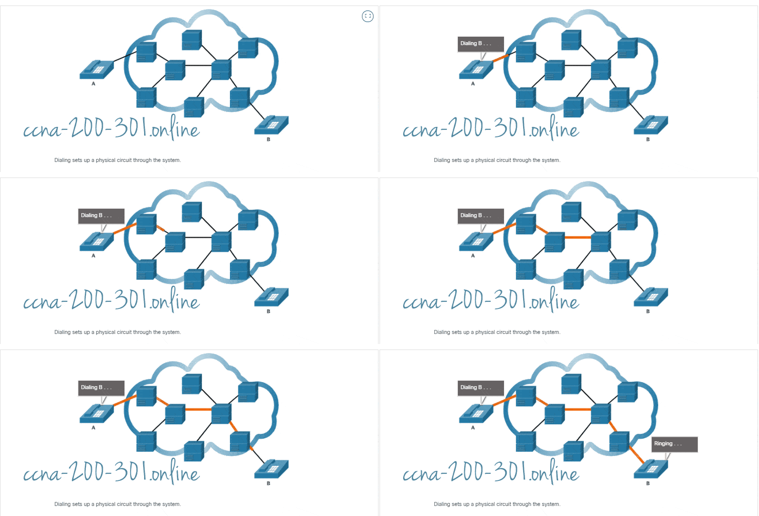
Network communication can be implemented using circuit-switched communication. A circuit-switched network establishes a dedicated circuit (or channel) between endpoints before the users can communicate.
Specifically, circuit switching dynamically establishes a dedicated virtual connection through the service provider network before voice or data communication can start.
For example, when a user makes a telephone call using a landline, the number called is used by the provider equipment to create a dedicated circuit from the caller to the called party.
During transmission over a circuit-switched network, all communication uses the same path. The entire fixed capacity allocated to the circuit is available for the duration of the connection, regardless of whether there is information to transmit or not. This can lead to inefficiencies in circuit usage. For this reason, circuit switching is generally not suited for data communication.
The two most common types of circuit-switched WAN technologies are the public switched telephone network (PSTN) and the legacy Integrated Services Digital Network (ISDN).
Click Play in the figure to see how circuit switching works.

Packet-Switched Communications
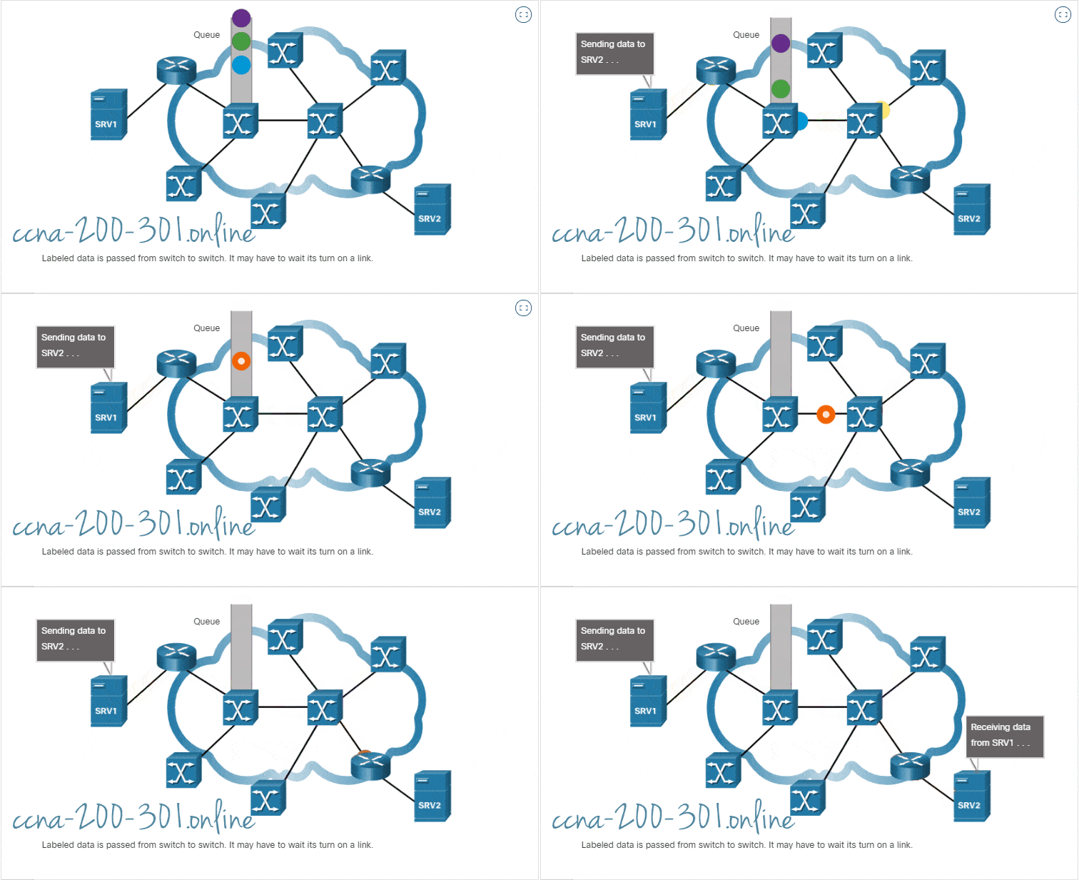
Network communication is most commonly implemented using packet-switched communication. In contrast to circuit-switching, packet-switching segments traffic data into packets that are routed over a shared network. Packet-switched networks do not require a circuit to be established, and they allow many pairs of nodes to communicate over the same channel.
Packet switching is much less expensive and more flexible than circuit switching. Although susceptible to delays (latency) and variability of delay (jitter), modern technology allows satisfactory transport of voice and video communications on these networks.
Common types of packet-switched WAN technologies are Ethernet WAN (Metro Ethernet), Multiprotocol Label Switching (MPLS), as well as legacy Frame Relay and legacy Asynchronous Transfer Mode (ATM).
Click Play in the figure to see a packet-switching example.

SDH, SONET, and DWDM
Service provider networks use fiber-optic infrastructures to transport user data between destinations. Fiber-optic cable is far superior to copper cable for long distance transmissions due to its much lower attenuation and interference.
There are two optical fiber OSI layer 1 standards available to service providers:
- SDH – Synchronous Digital Hierarchy (SDH) is a global standard for transporting data over fiber-optic cable.
- SONET – Synchronous Optical Networking (SONET) is the North American standard that provides the same services as SDH.
Both standards are essentially the same and therefore, they are often listed as SONET/SDH.
SDH/SONET define how to transfer multiple data, voice, and video communications over optical fiber using lasers or light-emitting diodes (LEDs) over great distances. Both standards are used on the ring network topology that contains the redundant fiber paths that allow traffic to flow in both directions.
Dense Wavelength Division Multiplexing (DWDM) is a newer technology that increases the data-carrying capacity of SDH and SONET by simultaneously sending multiple streams of data (multiplexing) using different wavelengths of light, as shown in the figure.

DWDM has the following features:
- It supports SONET and SDH standards.
- It can multiplex more than 80 different channels of data (i.e., wavelengths) onto a single fiber.
- Each channel is capable of carrying a 10 Gbps multiplexed signal.
- It assigns incoming optical signals to specific wavelengths of light (i.e., frequencies).
Ready to go! Keep visiting our networking course blog, give Like to our fanpage; and you will find more tools and concepts that will make you a networking professional.


