


Variable Length Subnet Masking
Summary
This topic explain how to create a flexible addressing scheme using variable length subnet masking (VLSM). Start learning CCNA 200-301 for free right now!!
Table of Contents
Video – VLSM Basics
As mentioned in the previous topic, public and private addresses affect the way you would subnet your network. There are also other issues that affect subnetting schemes. A standard /16 subnetting scheme creates subnets that each have the same number of hosts. Not every subnet you create will need this many hosts, leaving many IPv4 addresses unused. Perhaps you will need one subnet that contains many more hosts. This is why the variable-length subnet mask (VLSM) was developed.
Click Play to view a demonstration of basic VLSM techniques.
Video – VLSM Example
Click Play to view a demonstration of VLSM subnetting.
IPv4 Address Conservation
Because of the depletion of public IPv4 address space, making the most out of the available host addresses is a primary concern when subnetting IPv4 networks.
Using traditional subnetting, the same number of addresses is allocated for each subnet. If all the subnets have the same requirements for the number of hosts, or if conserving IPv4 address space is not an issue, these fixed-size address blocks would be efficient. Typically, with public IPv4 addresses, that is not the case.
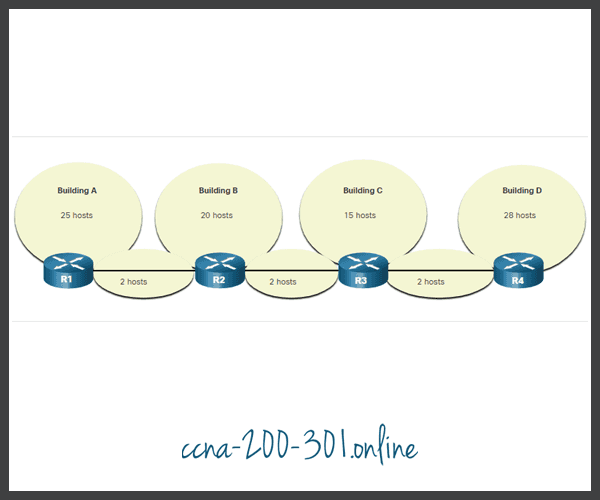
For example, the topology shown in the figure requires seven subnets, one for each of the four LANs, and one for each of the three connections between the routers.

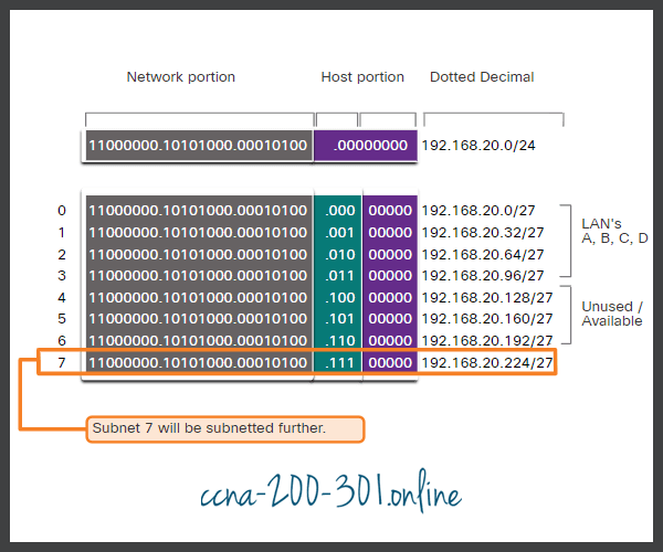
Using traditional subnetting with the given address of 192.168.20.0/24, three bits can be borrowed from the host portion in the last octet to meet the subnet requirement of seven subnets. As shown in the figure, borrowing 3 bits creates 8 subnets and leaves 5 host bits with 30 usable hosts per subnet. This scheme creates the needed subnets and meets the host requirement of the largest LAN.
Basic Subnet Scheme
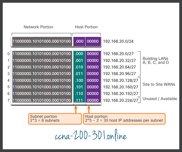
These seven subnets could be assigned to the LAN and WAN networks, as shown in the figure.

Although this traditional subnetting meets the needs of the largest LAN and divides the address space into an adequate number of subnets, it results in significant waste of unused addresses.
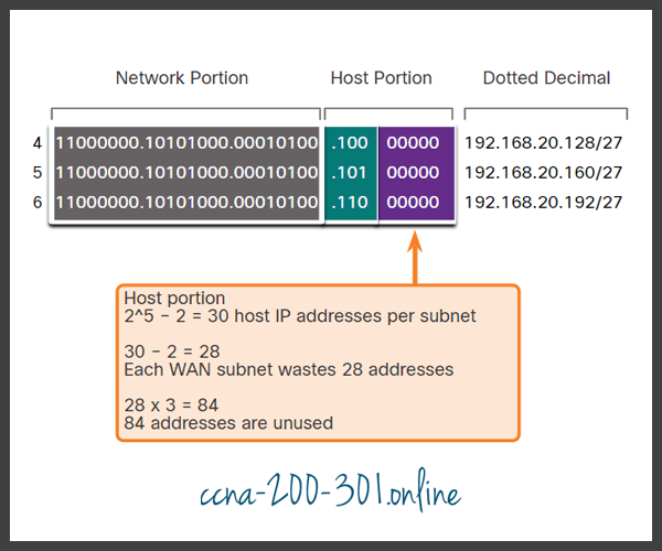
For example, only two addresses are needed in each subnet for the three WAN links. Because each subnet has 30 usable addresses, there are 28 unused addresses in each of these subnets. As shown in the figure, this results in 84 unused addresses (28×3).
Unused Addresses on WAN Subnets
Further, this limits future growth by reducing the total number of subnets available. This inefficient use of addresses is characteristic of traditional subnetting. Applying a traditional subnetting scheme to this scenario is not very efficient and is wasteful.
The variable-length subnet mask (VLSM) was developed to avoid wasting addresses by enabling us to subnet a subnet.
VLSM
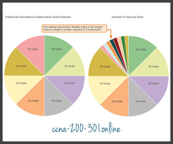
In all of the previous subnetting examples, the same subnet mask was applied for all the subnets. This means that each subnet has the same number of available host addresses. As illustrated in the left side of the figure, traditional subnetting creates subnets of equal size. Each subnet in a traditional scheme uses the same subnet mask. As shown in the right side of the figure, VLSM allows a network space to be divided into unequal parts. With VLSM, the subnet mask will vary depending on how many bits have been borrowed for a particular subnet, thus the “variable” part of the VLSM.
VLSM is just subnetting a subnet. The same topology used previously is shown in the figure. Again, we will use the 192.168.20.0/24 network and subnet it for seven subnets, one for each of the four LANs, and one for each of the three connections between the routers.
The figure shows how network 192.168.20.0/24 subnetted into eight equal-sized subnets with 30 usable host addresses per subnet. Four subnets are used for the LANs and three subnets could be used for the connections between the routers.
Basic Subnetting Scheme
However, the connections between the routers require only two host addresses per subnet (one host address for each router interface). Currently all subnets have 30 usable host addresses per subnet. To avoid wasting 28 addresses per subnet, VLSM can be used to create smaller subnets for the inter-router connections.
To create smaller subnets for the inter-router links, one of the subnets will be divided. In this example, the last subnet, 192.168.20.224/27, will be further subnetted. The figure shows the last subnet has been subnetted further by using the subnet mask 255.255.255.252 or /30.
VLSM Subnetting Scheme
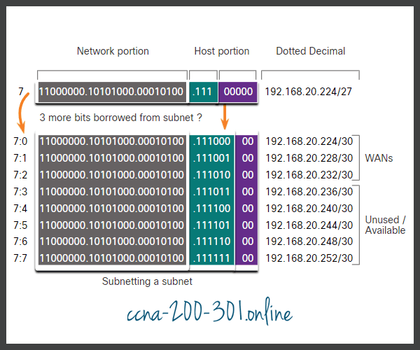
Why /30? Recall that when the number of needed host addresses is known, the formula 2n-2 (where n equals the number of host bits remaining) can be used. To provide two usable addresses, two host bits must be left in the host portion.
Because there are five host bits in the subnetted 192.168.20.224/27 address space, three more bits can be borrowed, leaving two bits in the host portion. The calculations at this point are exactly the same as those used for traditional subnetting. The bits are borrowed, and the subnet ranges are determined. The figure shows how the four /27 subnets have been assigned to the LANs and three of the /30 subnets have been assigned to the inter-router links.

This VLSM subnetting scheme reduces the number of addresses per subnet to a size appropriate for the networks that require fewer subnets. Subnetting subnet 7 for inter-router links, allows subnets 4, 5, and 6 to be available for future networks, as well as five additional subnets available for inter-router connections.
VLSM Topology Address Assignment
Using the VLSM subnets, the LAN and inter-router networks can be addressed without unnecessary waste.
The figure shows the network address assignments and the IPv4 addresses assigned to each router interface.
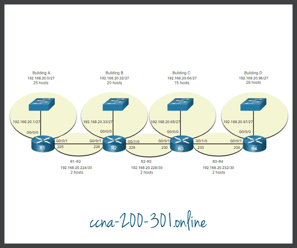
Using a common addressing scheme, the first host IPv4 address for each subnet is assigned to the LAN interface of the router. Hosts on each subnet will have a host IPv4 address from the range of host addresses for that subnet and an appropriate mask. Hosts will use the address of the attached router LAN interface as the default gateway address.
The table shows the network addresses and range of host addresses for each network. The default gateway address is displayed for the four LANs.
| Network Address | Range of Host Addresses | Default Gateway Address | |
|---|---|---|---|
| Building A | 192.168.20.0/27 | 192.168.20.1/27 to 192.168.20.30/27 | 192.168.20.1/27 |
| Building B | 192.168.20.32/27 | 192.168.20.33/27 to 192.168.20.62/27 | 192.168.20.33/27 |
| Building C | 192.168.20.64/27 | 192.168.20.65/27 to 192.168.20.94/27 | 192.168.20.65/27 |
| Building D | 192.168.20.96/27 | 192.168.20.97/27 to 192.168.20.126/27 | 192.168.20.97/27 |
| R1-R2 | 192.168.20.224/30 | 192.168.20.225/30 to 192.168.20.226/30 | |
| R2-R3 | 192.168.20.228/30 | 192.168.20.229/30 to 192.168.20.230/30 | |
| R3-R4 | 192.168.20.232/30 | 192.168.20.233/30 to 192.168.20.234/30 |
Ready to go! Keep visiting our networking course blog, give Like to our fanpage; and you will find more tools and concepts that will make you a networking professional.

