Troubleshooting IP Connectivity CCNA

Troubleshooting IP Connectivity

Troubleshooting IP Connectivity
5

Summary

This topic troubleshoot a network using the layered model. Start learning CCNA 200-301 for free right now!!

Note: Welcome: This topic is part of Module 12 of the Cisco CCNA 3 course, for a better follow up of the course you can go to the CCNA 3 section to guide you through an order.

Components of Troubleshooting End-to-End Connectivity

This topic presents a single topology and the tools to diagnose, and in some cases solve, an end-to-end connectivity problem. Diagnosing and solving problems is an essential skill for network administrators. There is no single recipe for troubleshooting, and a problem can be diagnosed in many ways. However, by employing a structured approach to the troubleshooting process, an administrator can reduce the time it takes to diagnose and solve a problem.

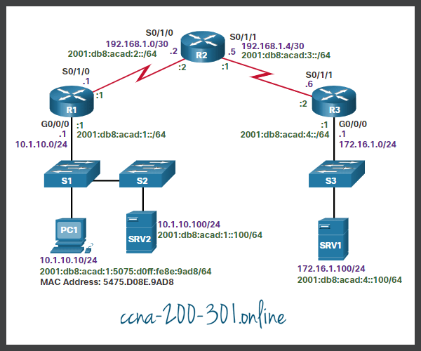
Throughout this topic, the following scenario is used. The client host PC1 is unable to access applications on Server SRV1 or Server SRV2. The figure shows the topology of this network. PC1 uses SLAAC with EUI-64 to create its IPv6 global unicast address. EUI-64 creates the Interface ID using the Ethernet MAC address, inserting FFFE in the middle, and flipping the seventh bit.

Troubleshooting End-to-End Connectivity

When there is no end-to-end connectivity, and the administrator chooses to troubleshoot with a bottom-up approach, the following are common steps the administrator can take:

  • Step 1. Check physical connectivity at the point where network communication stops. This includes cables and hardware. The problem might be with a faulty cable or interface, or involve misconfigured or faulty hardware.
  • Step 2. Check for duplex mismatches.
  • Step 3. Check data link and network layer addressing on the local network. This includes IPv4 ARP tables, IPv6 neighbor tables, MAC address tables, and VLAN assignments.
  • Step 4. Verify that the default gateway is correct.
  • Step 5. Ensure that devices are determining the correct path from the source to the destination. Manipulate the routing information if necessary.
  • Step 6. Verify the transport layer is functioning properly. Telnet can also be used to test transport layer connections from the command line.
  • Step 7. Verify that there are no ACLs blocking traffic.
  • Step 8. Ensure that DNS settings are correct. There should be a DNS server that is accessible.

The outcome of this process is operational, end-to-end connectivity. If all the steps have been performed without any resolution, the network administrator may either want to repeat the previous steps or escalate the problem to a senior administrator.

End-to-End Connectivity Problem Initiates Troubleshooting

Usually what initiates a troubleshooting effort is the discovery that there is a problem with end-to-end connectivity. Two of the most common utilities used to verify a problem with end-to-end connectivity are ping and traceroute, as shown in the figure.

End-to-End Connectivity Problem

Click each button to review the ping, traceroute, and tracert utilities.


Ping is probably the most widely-known connectivity-testing utility in networking and has always been part of Cisco IOS Software. It sends out requests for responses from a specified host address. The ping command uses a Layer 3 protocol that is a part of the TCP/IP suite called ICMP. Ping uses the ICMP echo request and ICMP echo reply packets. If the host at the specified address receives the ICMP echo request, it responds with an ICMP echo reply packet. Ping can be used to verify end-to-end connectivity for both IPv4 and IPv6. The command output shows a successful ping from PC1 to SRV1, at address 172.16.1.100.

C:\> ping 172.16.1.100
Pinging 172.16.1.100 with 32 bytes of data:
Reply from 172.16.1.100: bytes=32 time=199ms TTL=128
Reply from 172.16.1.100: bytes=32 time=193ms TTL=128
Reply from 172.16.1.100: bytes=32 time=194ms TTL=128
Reply from 172.16.1.100: bytes=32 time=196ms TTL=128
Ping statistics for 172.16.1.100:
    Packets: Sent = 4, Received = 4, Lost = 0 (0% loss),
Approximate round trip times in milli-seconds:
    Minimum = 193ms, Maximum = 199ms, Average = 195ms
C:\>

Like the ping command, the Cisco IOS traceroute command can be used for both IPv4 and IPv6. The tracert command is used with Windows operating systems. The trace generates a list of hops, router IP addresses and the destination IP address that are successfully reached along the path. This list provides important verification and troubleshooting information. If the data reaches the destination, the trace lists the interface on every router in the path. If the data fails at some hop along the way, the address of the last router that responded to the trace is known. This address is an indication of where the problem or security restrictions reside.

The tracert output illustrates the path the IPv4 packets take to reach their destination.

C:\> tracert 172.16.1.100
Tracing route to 172.16.1.100 over a maximum of 30 hops:
  1     1 ms    <1 ms    <1 ms  10.1.10.1
  2     2 ms     2 ms     1 ms  192.168.1.2
  3     2 ms     2 ms     1 ms  192.168.1.6
  4     2 ms     2 ms     1 ms  172.16.1.100
Trace complete.
C:\>

When using these utilities, the Cisco IOS utility recognizes whether the address is an IPv4 or IPv6 address and uses the appropriate protocol to test connectivity. The command output shows the ping and traceroute commands on router R1 used to test IPv6 connectivity.

R1# ping 2001:db8:acad:4::100 
Type escape sequence to abort.
Sending 5, 100-byte ICMP Echos to 2001:DB8:ACAD:4::100, timeout is 2 seconds:
!!!!!
Success rate is 100 percent (5/5), round-trip min/avg/max = 56/56/56 ms
R1#
R1# traceroute 2001:db8:acad:4::100 
Type escape sequence to abort.
Tracing the route to 2001:DB8:ACAD:4::100
1.   2001:DB8:ACAD:2::2 20 msec 20 msec 20 msec
2.   2001:DB8:ACAD:3::2 44 msec 40 msec 40 msec 
R1#

Note: The traceroute command is commonly performed when the ping command fails. If the ping succeeds, the traceroute command is commonly not needed because the technician knows that connectivity exists.

Step 1 – Verify the Physical Layer

All network devices are specialized computer systems. At a minimum, these devices consist of a CPU, RAM, and storage space, allowing the device to boot and run the operating system and interfaces. This allows for the reception and transmission of network traffic. When a network administrator determines that a problem exists on a given device, and that problem might be hardware-related, it is worthwhile to verify the operation of these generic components. The most commonly used Cisco IOS commands for this purpose are show processes cpushow memory, and show interfaces. This topic discusses the show interfaces command.

When troubleshooting performance-related issues and hardware is suspected to be at fault, the show interfaces command can be used to verify the interfaces through which the traffic passes.

Refer to the command output of the show interfaces command.

R1# show interfaces GigabitEthernet 0/0/0
GigabitEthernet0/0/0 is up, line protocol is up 
Hardware is CN Gigabit Ethernet, address is d48c.b5ce.a0c0(bia d48c.b5ce.a0c0) 
Internet address is 10.1.10.1/24 
(Output omitted)
Input queue: 0/75/0/0 (size/max/drops/flushes); Total output drops: 0
Queueing strategy: fifo 
 Output queue: 0/40 (size/max) 
5 minute input rate 0 bits/sec, 0 packets/sec 
5 minute output rate 0 bits/sec, 0 packets/sec 
85 packets input, 7711 bytes, 0 no buffer 
Received 25 broadcasts (0 IP multicasts)
0 runts, 0 giants, 0 throttles
0 input errors, 0 CRC, 0 frame, 0 overrun, 0 ignored 
0 watchdog, 5 multicast, 0 pause input 
10112 packets output, 922864 bytes, 0 underruns 
0 output errors, 0 collisions, l interface resets 
11 unknown protocol drops 
0 babbles, 0 late collision, 0 deferred 
0 lost carrier, 0 no carrier, 0 pause output 
0 output buffer failures, 0 output buffers swapped out 
R1#

Click each button for an explanation of the highlighted output.

Input queue drops (and the related ignored and throttle counters) signify that at some point, more traffic was delivered to the router than it could process. This does not necessarily indicate a problem. That could be normal traffic during peak periods. However, it could be an indication that the CPU cannot process packets in time, so if this number is consistently high, it is worth trying to spot at which moments these counters are increasing and how this relates to CPU usage.

Output queue drops indicate that packets were dropped due to congestion on the interface. Seeing output drops is normal for any point where the aggregate input traffic is higher than the output traffic. During peak traffic periods, packets are dropped if traffic is delivered to the interface faster than it can be sent out. However, even if this is considered normal behavior, it leads to packet drops and queuing delays, so applications that are sensitive to those, such as VoIP, might suffer from performance issues. Consistently seeing output queue drops can be an indicator that you need to implement an advanced queuing mechanism to implement or modify QoS.

Input errors indicate errors that are experienced during the reception of the frame, such as CRC errors. High numbers of CRC errors could indicate cabling problems, interface hardware problems, or, in an Ethernet-based network, duplex mismatches.

Output errors indicate errors, such as collisions, during the transmission of a frame. In most Ethernet-based networks today, full-duplex transmission is the norm, and half-duplex transmission is the exception. In full-duplex transmission, operation collisions cannot occur; therefore, collisions (especially late collisions) often indicate duplex mismatches.

Step 2 – Check for Duplex Mismatches

Another common cause for interface errors is a mismatched duplex mode between two ends of an Ethernet link. In many Ethernet-based networks, point-to-point connections are now the norm, and the use of hubs and the associated half-duplex operation is becoming less common. This means that most Ethernet links today operate in full-duplex mode, and while collisions were normal for an Ethernet link, collisions today often indicate that duplex negotiation has failed, or the link is not operating in the correct duplex mode.

The IEEE 802.3ab Gigabit Ethernet standard mandates the use of autonegotiation for speed and duplex. In addition, although it is not strictly mandatory, practically all Fast Ethernet NICs also use autonegotiation by default. The use of autonegotiation for speed and duplex is the current recommended practice.

However, if duplex negotiation fails for some reason, it might be necessary to set the speed and duplex manually on both ends. Typically, this would mean setting the duplex mode to full-duplex on both ends of the connection. If this does not work, running half-duplex on both ends is preferred over a duplex mismatch.

Duplex configuration guidelines include the following:

  • Autonegotiation of speed and duplex is recommended.
  • If autonegotiation fails, manually set the speed and duplex on interconnecting ends.
  • Point-to-point Ethernet links should always run in full-duplex mode.
  • Half-duplex is uncommon and typically encountered only when legacy hubs are used.

Troubleshooting Example

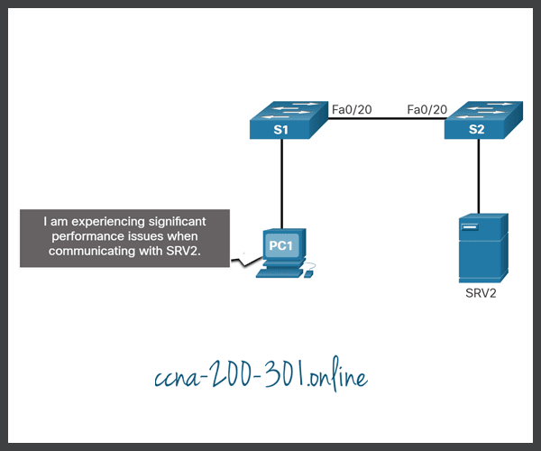
In the previous scenario, the network administrator needed to add additional users to the network. To incorporate these new users, the network administrator installed a second switch and connected it to the first. Soon after S2 was added to the network, users on both switches began experiencing significant performance problems connecting with devices on the other switch, as shown in the figure.

Troubleshooting Example

The network administrator notices a console message on switch S2:

*Mar 1 00:45:08.756: %CDP-4-DUPLEX_MISMATCH: duplex mismatch discovered on FastEthernet0/20 (not half duplex), with Switch FastEthernet0/20 (half duplex).

Using the show interfaces fa 0/20 command, the network administrator examines the interface on S1 that is used to connect to S2 and notices it is set to full-duplex, as shown the command output.

S1# show interface fa 0/20
FastEthernet0/20 is up, line protocol is up (connected) 
Hardware is Fast Ethernet, address is 0cd9.96e8.8a01 (bia 0cd9.96e8.8a01)
MTU 1500 bytes, BW 10000 Kbit/sec, DLY 1000 usec, reliability 255/255, txload 1/255, rxload 1/255 
Encapsulation ARPA, loopback not set Keepalive set (10 sec)
Full-duplex, Auto-speed, media type is 10/100BaseTX 
  
(Output omitted)
  
S1#

The network administrator now examines the other side of the connection, the port on S2. The command out shows that this side of the connection has been configured for half-duplex.

S2# show interface fa 0/20
FastEthernet0/20 is up, line protocol is up (connected) 
Hardware is Fast Ethernet, address is 0cd9.96d2.4001 (bia 0cd9.96d2.4001)
MTU 1500 bytes, BW 100000 Kbit/sec, DLY 100 usec, reliability 255/255, txload 1/255, rxload 1/255 
Encapsulation ARPA, loopback not set Keepalive set (10 sec)
Half-duplex, Auto-speed, media type is 10/100BaseTX 
  
(Output omitted)
  
S2(config)# interface fa 0/20 
S2(config-if)# duplex auto 
S2(config-if)#

The network administrator corrects the setting to duplex auto to automatically negotiate the duplex. Because the port on S1 is set to full-duplex, S2 also uses full-duplex.

The users report that there are no longer any performance problems.

Step 3 – Verify Addressing on the Local Network

When troubleshooting end-to-end connectivity, it is useful to verify mappings between destination IP addresses and Layer 2 Ethernet addresses on individual segments. In IPv4, this functionality is provided by ARP. In IPv6, the ARP functionality is replaced by the neighbor discovery process and ICMPv6. The neighbor table caches IPv6 addresses and their resolved Ethernet physical (MAC) addresses.

Click each button for an example and explanation of the command to verify Layer 2 and Layer 3 addressing.

The arp Windows command displays and modifies entries in the ARP cache that are used to store IPv4 addresses and their resolved Ethernet physical (MAC) addresses. As shown in the command output, the arp Windows command lists all devices that are currently in the ARP cache.

The information that is displayed for each device includes the IPv4 address, physical (MAC) address, and the type of addressing (static or dynamic).

The cache can be cleared by using the arp -d Windows command if the network administrator wants to repopulate the cache with updated information.

Note: The arp commands in Linux and MAC OS X have a similar syntax.

C:\> arp -a
Interface: 10.1.10.100 --- 0xd
  Internet Address      Physical Address      Type
  10.1.10.1             d4-8c-b5-ce-a0-c0    dynamic
  224.0.0.22            01-00-5e-00-00-16     static
  224.0.0.251           01-00-5e-00-00-fb     static
  239.255.255.250       01-00-5e-7f-ff-fa     static
  255.255.255.255       ff-ff-ff-ff-ff-ff     static
C:\>

The netsh interface ipv6 show neighbor Windows command output lists all devices that are currently in the neighbor table.

The information that is displayed for each device includes the IPv6 address, physical (MAC) address, and the type of addressing. By examining the neighbor table, the network administrator can verify that destination IPv6 addresses map to correct Ethernet addresses. The IPv6 link-local addresses on all interfaces of R1 have been manually configured to FE80::1. Similarly, R2 has been configured with the link-local address of FE80::2 on its interfaces and R3 has been configured with the link-local address of FE80::3 on its interfaces. Remember, link-local addresses must be unique on the link or network.

Note: The neighbor table for Linux and MAC OS X can be displayed using ip neigh show command.

C:\> netsh interface ipv6 show neighbor 
Internet Address                              Physical Address   Type
--------------------------------------------  -----------------  -----------
fe80::9657:a5ff:fe0c:5b02                     94-57-a5-0c-5b-02  Stale
fe80::1                                       d4-8c-b5-ce-a0-c0  Reachable (Router)
ff02::1                                       33-33-00-00-00-01  Permanent
ff02::2                                       33-33-00-00-00-02  Permanent
ff02::16                                      33-33-00-00-00-16  Permanent
ff02::1:2                                     33-33-00-01-00-02  Permanent
ff02::1:3                                     33-33-00-01-00-03  Permanent
ff02::1:ff0c:5b02                             33-33-ff-0c-5b-02  Permanent
ff02::1:ff2d:a75e                             33-33-ff-2d-a7-5e  Permanent

The show ipv6 neighbors command output displays an example of the neighbor table on the Cisco IOS router.

Note: The neighbor states for IPv6 are more complex than the ARP table states in IPv4. Additional information is contained in RFC 4861.

R1# show ipv6 neighbors 
IPv6 Address                        Age  Link-layer Addr   State  Interface
FE80::21E:7AFF:FE79:7A81              8  001e.7a79.7a81    STALE  Gi0/0
2001:DB8:ACAD:1:5075:D0FF:FE8E:9AD8   0  5475.d08e.9ad8    REACH  Gi0/0

When a destination MAC address is found in the switch MAC address table, the switch forwards the frame only to the port of the device that has that MAC address. To do this, the switch consults its MAC address table. The MAC address table lists the MAC address connected to each port. Use the show mac address-table command to display the MAC address table on the switch. An example of a switch MAC address table is shown in the command output.

Notice how the MAC address for PC1, a device in VLAN 10, has been discovered along with the S1 switch port to which PC1 attaches. Remember, the MAC address table of switch only contains Layer 2 information, including the Ethernet MAC address and the port number. IP address information is not included.

S1# show mac address-table
              Mac Address Table
--------------------------------------------
Vlan      Mac Address         Type     Ports
All       0100.0ccc.cccc      STATIC   CPU
All       0100.0ccc.cccd      STATIC   CPU
10        d48c.b5ce.a0c0      DYNAMIC  Fa0/4
10        000f.34f9.9201      DYNAMIC  Fa0/5
10        5475.d08e.9ad8      DYNAMIC  Fa0/13
Total Mac Addresses for this criterion: 5

Troubleshoot VLAN Assignment Example

Another issue to consider when troubleshooting end-to-end connectivity is VLAN assignment. In the switched network, each port in a switch belongs to a VLAN. Each VLAN is considered a separate logical network, and packets destined for stations that do not belong to the VLAN must be forwarded through a device that supports routing. If a host in one VLAN sends a broadcast Ethernet frame, such as an ARP request, all hosts in the same VLAN receive the frame; hosts in other VLANs do not. Even if two hosts are in the same IP network, they will not be able to communicate if they are connected to ports assigned to two separate VLANs. Additionally, if the VLAN to which the port belongs is deleted, the port becomes inactive. All hosts attached to ports belonging to the VLAN that was deleted are unable to communicate with the rest of the network. Commands such as show vlan can be used to validate VLAN assignments on a switch.

Assume for example, that in an effort to improve the wire management in the wiring closet, your company has reorganized the cables connecting to switch S1. Almost immediately afterward, users started calling the support desk stating that they could no longer reach devices outside their own network.

Click each button for an explanation of the process used to troubleshoot this issue.

An examination of PC1 ARP table using the arp Windows command shows that the ARP table no longer contains an entry for the default gateway 10.1.10.1, as shown in the command output.

C:\> arp -a
Interface: 10.1.10.100 --- 0xd
  Internet Address      Physical Address      Type
  224.0.0.22            01-00-5e-00-00-16     static
  224.0.0.251           01-00-5e-00-00-fb     static
  239.255.255.250       01-00-5e-7f-ff-fa     static
  255.255.255.255       ff-ff-ff-ff-ff-ff     static
C:\>

There were no configuration changes on the router, so S1 is the focus of the troubleshooting.

The MAC address table for S1, as shown in the command output, shows that the MAC address for R1 is on a different VLAN than the rest of the 10.1.10.0/24 devices, including PC1.

S1# show mac address-table
              Mac Address Table
--------------------------------------------
Vlan      Mac Address         Type     Ports
All       0100.0ccc.cccc      STATIC   CPU
All       0100.0ccc.cccd      STATIC   CPU
 1        d48c.b5ce.a0c0      DYNAMIC  Fa0/1
10        000f.34f9.9201      DYNAMIC  Fa0/5
10        5475.d08e.9ad8      DYNAMIC  Fa0/13
Total Mac Addresses for this criterion: 5
S1#

During the re-cabling, the patch cable for R1 was moved from Fa 0/4 on VLAN 10 to Fa 0/1 on VLAN 1. After the network administrator configured the Fa 0/1 port of S1 to be on VLAN 10, as shown in the command output, the problem was resolved. The MAC address table now shows VLAN 10 for the MAC address of R1 on port Fa 0/1.

S1(config)# interface fa0/1
S1(config-if)# switchport mode access
S1(config-if)# switchport access vlan 10
S1(config-if)# exit
S1# 
S1# show mac address-table
              Mac Address Table
--------------------------------------------
Vlan      Mac Address         Type     Ports
All       0100.0ccc.cccc      STATIC   CPU
All       0100.0ccc.cccd      STATIC   CPU
10        d48c.b5ce.a0c0      DYNAMIC  Fa0/1
10        000f.34f9.9201      DYNAMIC  Fa0/5
10        5475.d08e.9ad8      DYNAMIC  Fa0/13
Total Mac Addresses for this criterion: 5
S1#

Step 4 – Verify Default Gateway

If there is no detailed route on the router, or if the host is configured with the wrong default gateway, then communication between two endpoints in different networks does not work.

The figure illustrates how PC1 uses R1 as its default gateway. Similarly, R1 uses R2 as its default gateway or gateway of last resort. If a host needs access to resources beyond the local network, the default gateway must be configured. The default gateway is the first router on the path to destinations beyond the local network.

Verify Default Gateway

Troubleshooting IPv4 Default Gateway Example

In this example, R1 has the correct default gateway, which is the IPv4 address of R2. However, PC1 has the wrong default gateway. PC1 should have the default gateway of R1 10.1.10.1. This must be configured manually if the IPv4 addressing information was manually configured on PC1. If the IPv4 addressing information was obtained automatically from a DHCPv4 server, then the configuration on the DHCP server must be examined. A configuration problem on a DHCP server usually affects multiple clients.

Click each button to view the command output for R1 and PC1.

The command output of the show ip route Cisco IOS command is used to verify the default gateway of R1

R1# show ip route | include Gateway|0.0.0.0
  
Gateway of last resort is 192.168.1.2 to network 0.0.0.0 
S* 0.0.0.0/0 [1/0] via 192.168.1.2
  
R1#

On a Windows host, the route print Windows command is used to verify the presence of the IPv4 default gateway as shown in the command output.

C:\> route print
(Output omitted)
  
IPv4 Route Table
===========================================================================
Active Routes:
Network Destination        Netmask          Gateway       Interface  Metric
          0.0.0.0          0.0.0.0        10.1.10.1      10.1.10.10      11
(Output omitted)

Troubleshoot IPv6 Default Gateway Example

In IPv6, the default gateway can be configured manually, using stateless autoconfiguration (SLAAC), or by using DHCPv6. With SLAAC, the default gateway is advertised by the router to hosts using ICMPv6 Router Advertisement (RA) messages. The default gateway in the RA message is the link-local IPv6 address of a router interface. If the default gateway is configured manually on the host, which is very unlikely, the default gateway can be set to either the global IPv6 address, or to the link-local IPv6 address.

Click each button for an example and explanation of troubleshooting an IPv6 default gateway issue.

As shown in the command output, the show ipv6 route Cisco IOS command is used to check for the IPv6 default route on R1. R1 has a default route via R2.

R1# show ipv6 route
  
(Output omitted)
  
S ::/0 [1/0]
via 2001:DB8:ACAD:2::2
R1#

The ipconfig Windows command is used to verify that a PC1 has an IPv6 default gateway. In the command output, PC1 is missing an IPv6 global unicast address and an IPv6 default gateway. PC1 is enabled for IPv6 because it has an IPv6 link-local address. The link-local address is automatically created by the device. Checking the network documentation, the network administrator confirms that hosts on this LAN should be receiving their IPv6 address information from the router using SLAAC.

Note: In this example, other devices on the same LAN using SLAAC would also experience the same problem receiving IPv6 address information.

C:\> ipconfig 
Windows IP Configuration
   Connection-specific DNS Suffix . :
   Link-local IPv6 Address . . . .  : fe80::5075:d0ff:fe8e:9ad8%13
   IPv4 Address . . . . . . . . . . : 10.1.10.10 
   Subnet Mask  . . . . . . . . . . : 255.255.255.0
   Default Gateway. . . . . . . . . : 10.1.10.1
C:\>

The command output of the show ipv6 interface GigabitEthernet 0/0/0 on R1 reveals that although the interface has an IPv6 address, it is not a member of the All-IPv6-Routers multicast group FF02::2. This means the router is not enabled as an IPv6 router. Therefore, it is not sending out ICMPv6 RAs on this interface.

R1# show ipv6 interface GigabitEthernet 0/0/0
GigabitEthernet0/0/0 is up, line protocol is up 
  IPv6 is enabled, link-local address is FE80::1 
  No Virtual link-local address(es):
  Global unicast address(es):
    2001:DB8:ACAD:1::1, subnet is 2001:DB8:ACAD:1::/64
  Joined group address(es):
      FF02:: 1
      FF02::1:FF00:1
  
(Output omitted)
R1#

R1 is enabled as an IPv6 router using the ipv6 unicast-routing command. The show ipv6 interface GigabitEthernet 0/0/0 command verifies that R1 is a member of ff02::2, the All-IPv6-Routers multicast group.

R1(config)# ipv6 unicast-routing
R1(config)# exit
R1# show ipv6 interface GigabitEthernet 0/0/0 
GigabitEthernet0/0/0 is up, line protocol is up 
  IPv6 is enabled, link-local address is FE80::1 
  No Virtual link-local address(es):
  Global unicast address(es):
    2001:DB8:ACAD:1::1, subnet is 2001:DB8:ACAD:1::/64
  Joined group address(es):
      FF02:: 1
      FF02:: 2
      FF02::1:FF00:1
(Output omitted)
R1#

To verify that PC1 has the default gateway set, use the ipconfig command on the Microsoft Windows PC or the ifconfig command on Linux and Mac OS X. In the, PC1 has an IPv6 global unicast address and an IPv6 default gateway. The default gateway is set to the link-local address of router R1, fe80::1.

C:\> ipconfig 
Windows IP Configuration
   Connection-specific DNS Suffix . :
   IPv6 Address. . . . . . . . . .  : 2001:db8:acad:1:5075:d0ff:fe8e:9ad8
   Link-local IPv6 Address . . . .  : fe80::5075:d0ff:fe8e:9ad8%13
   IPv4 Address . . . . . . . . . . : 10.1.10.10 
   Subnet Mask  . . . . . . . . . . : 255.255.255.0
   Default Gateway. . . . . . . . . : fe80::1
                                      10.1.10.1
C:\>

Step 5 – Verify Correct Path

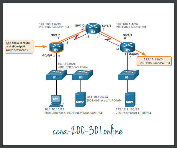
When troubleshooting, it is often necessary to verify the path to the destination network. The figure shows the reference topology indicating the intended path for packets from PC1 to SRV1.

Verify Correct Path
Verify Correct Path

The routers in the path make the routing decision based on information in the routing tables. Click each button to view the IPv4 and IPv6 routing tables for R1.

R1# show ip route | begin Gateway
Gateway of last resort is 192.168.1.2 to network 0.0.0.0
O*E2  0.0.0.0/0 [110/1] via 192.168.1.2, 00:00:13, Serial0/1/0
      10.0.0.0/8 is variably subnetted, 2 subnets, 2 masks
C        10.1.10.0/24 is directly connected, GigabitEthernet0/0/0
L        10.1.10.1/32 is directly connected, GigabitEthernet0/0/0
      172.16.0.0/24 is subnetted, 1 subnets
O        172.16.1.0 [110/100] via 192.168.1.2, 00:01:59, Serial0/1/0
      192.168.1.0/24 is variably subnetted, 3 subnets, 2 masks
C        192.168.1.0/30 is directly connected, Serial0/1/0
L        192.168.1.1/32 is directly connected, Serial0/1/0
O        192.168.1.4/30 [110/99] via 192.168.1.2, 00:06:25, Serial0/1/0
R1#

R1# show ipv6 route
IPv6 Routing Table - default - 8 entries
Codes: C - Connected, L - Local, S - Static, U - Per-user Static route
       B - BGP, R - RIP, H - NHRP, I1 - ISIS L1
       I2 - ISIS L2, IA - ISIS interarea, IS - ISIS summary, D - EIGRP
       EX - EIGRP external, ND - ND Default, NDp - ND Prefix, DCE - Destination
       NDr - Redirect, O - OSPF Intra, OI - OSPF Inter, OE1 - OSPF ext 1
       OE2 - OSPF ext 2, ON1 - OSPF NSSA ext 1, ON2 - OSPF NSSA ext 2
       a - Application
OE2 ::/0 [110/1], tag 1
     via FE80::2, Serial0/1/0
C   2001:DB8:ACAD:1::/64 [0/0]
     via GigabitEthernet0/0/0, directly connected
L   2001:DB8:ACAD:1::1/128 [0/0]
     via GigabitEthernet0/0/0, receive
C   2001:DB8:ACAD:2::/64 [0/0]
     via Serial0/1/0, directly connected
L   2001:DB8:ACAD:2::1/128 [0/0]
     via Serial0/1/0, receive
O   2001:DB8:ACAD:3::/64 [110/99]
     via FE80::2, Serial0/1/0
O   2001:DB8:ACAD:4::/64 [110/100]
     via FE80::2, Serial0/1/0
L   FF00::/8 [0/0]
     via Null0, receive
R1#

The IPv4 and IPv6 routing tables can be populated by the following methods:

  • Directly connected networks
  • Local host or local routes
  • Static routes
  • Dynamic routes
  • Default routes

The process of forwarding IPv4 and IPv6 packets is based on the longest bit match or longest prefix match. The routing table process will attempt to forward the packet using an entry in the routing table with the greatest number of leftmost matching bits. The number of matching bits is indicated by the prefix length of the route.

The figure describes the process for both the IPv4 and IPv6 routing tables.

Process IPv4 and IPv6 routing tables

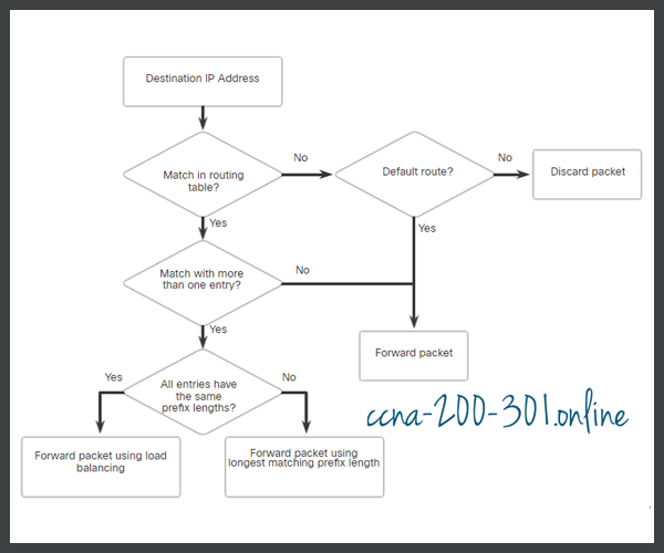
Examine the following scenarios based on the flow chart above. If the destination address in a packet:

  • Does not match an entry in the routing table, then the default route is used. If there is not a default route that is configured, the packet is discarded.
  • Matches a single entry in the routing table, then the packet is forwarded through the interface that is defined in this route.
  • Matches more than one entry in the routing table and the routing entries have the same prefix length, then the packets for this destination can be distributed among the routes that are defined in the routing table.
  • Matches more than one entry in the routing table and the routing entries have different prefix lengths, then the packets for this destination are forwarded out of the interface that is associated with the route that has the longer prefix match.

Troubleshooting Example

Devices are unable to connect to the server SRV1 at 172.16.1.100. Using the show ip route command, the administrator should check to see if a routing entry exists to network 172.16.1.0/24. If the routing table does not have a specific route to the SRV1 network, the network administrator must then check for the existence of a default or summary route entry in the direction of the 172.16.1.0/24 network. If none exists, then the problem may be with routing and the administrator must verify that the network is included within the dynamic routing protocol configuration or add a static route.

Step 6 – Verify the Transport Layer

If the network layer appears to be functioning as expected, but users are still unable to access resources, then the network administrator must begin troubleshooting the upper layers. Two of the most common issues that affect transport layer connectivity include ACL configurations and NAT configurations. A common tool for testing transport layer functionality is the Telnet utility.

Caution: While Telnet can be used to test the transport layer, for security reasons, SSH should be used to remotely manage and configure devices.

Troubleshooting Example

A network administrator is troubleshooting a problem where they cannot connect to a router using HTTP. The administrator pings R2 as shown in the command output.

R1# ping 2001:db8:acad:2::2
Type escape sequence to abort.
Sending 5, 100-byte ICMP Echos to 2001:DB8:ACAD:2::2, timeout is 2 seconds:
!!!!!
Success rate is 100 percent (5/5), round-trip min/avg/max = 2/2/3 ms
R1#

R2 responds and confirms that the network layer, and all layers below the network layer are operational. The administrator knows the issue is with Layer 4 or up and must start troubleshooting those layers.

Next, the administrator verifies that they can Telnet to R2 as shown in the command output.

R1# telnet 2001:db8:acad:2::2
Trying 2001:DB8:ACAD:2::2 ... Open
User Access Verification
Password:
R2> exit
[Connection to 2001:db8:acad:2::2 closed by foreign host]
R1#

The administrator has confirmed that Telnet services is running on R2. Although the Telnet server application runs on its own well-known port number 23 and Telnet clients connect to this port by default, a different port number can be specified on the client to connect to any TCP port that must be tested. Using a different port other than TCP port 23 indicates whether the connection is accepted (as indicated by the word “Open” in the output), refused, or times out. From any of those responses, further conclusions can be made concerning the connectivity. Certain applications, if they use an ASCII-based session protocol, might even display an application banner, it may be possible to trigger some responses from the server by typing in certain keywords, such as with SMTP, FTP, and HTTP.

For example, the administrator attempts to Telnet to R2 using port 80.

R1# telnet 2001:db8:acad:2::2 80
Trying 2001:DB8:ACAD:2::2, 80 ... Open
^C
HTTP/1.1 400 Bad Request
Date: Mon, 04 Nov 2019 12:34:23 GMT
Server: cisco-IOS
Accept-Ranges: none
400 Bad Request
[Connection to 2001:db8:acad:2::2 closed by foreign host]
R1#

The output verifies a successful transport layer connection, but R2 is refusing the connection using port 80.

Step 7 – Verify ACLs

On routers, there may be ACLs that prohibit protocols from passing through the interface in the inbound or outbound direction.

Use the show ip access-lists command to display the contents of all IPv4 ACLs and the show ipv6 access-list command to display the contents of all IPv6 ACLs configured on a router. The specific ACL can be displayed by entering the ACL name or number as an option for this command. The show ip interfaces and show ipv6 interfaces commands display IPv4 and IPv6 interface information that indicates whether any IP ACLs are set on the interface.

Troubleshooting Example

To prevent spoofing attacks, the network administrator decided to implement an ACL that is preventing devices with a source network address of 172.16.1.0/24 from entering the inbound S0/0/1 interface on R3, as shown in the figure. All other IP traffic should be allowed.

Verify ACLs
Verify ACLs

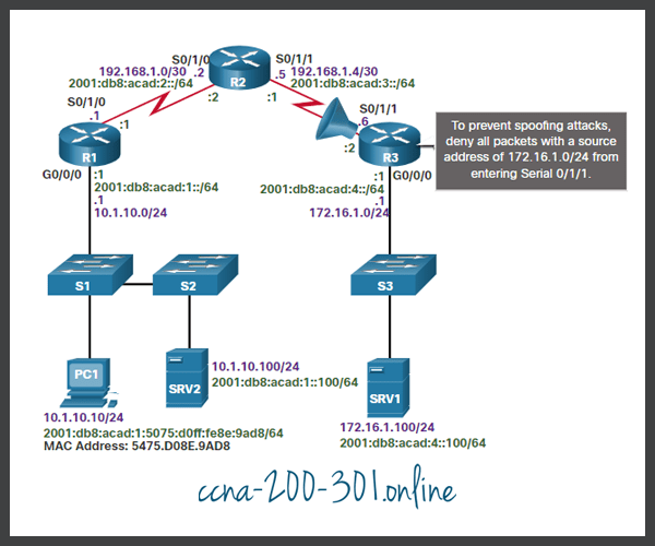
However, shortly after implementing the ACL, users on the 10.1.10.0/24 network were unable to connect to devices on the 172.16.1.0/24 network, including SRV1.

Click each button for an example of how to troubleshoot this issue.

The show ip access-lists command displays that the ACL is configured correctly, as shown in the command output.

R3# show ip access-lists
Extended IP access list 100
    10 deny ip 172.16.1.0 0.0.0.255 any (108 matches)
    20 permit ip any any (28 matches)
R3#

We can verify which interface has the ACL applied using the show ip interfaces serial 0/1/1 command and the show ip interfaces serial 0/0/0 command. The output reveals that the ACL was never applied to the inbound interface on Serial 0/0/1 but it was accidentally applied to the G0/0/0 interface, blocking all outbound traffic from the 172.16.1.0/24 network.

R3# show ip interface serial 0/1/1 | include access list
  Outgoing Common access list is not set
  Outgoing access list is not set
  Inbound Common access list is not set
  Inbound  access list is not set
R3#
R3# show ip interface gig 0/0/0 | include access list
  Outgoing Common access list is not set
  Outgoing access list is not set
  Inbound Common access list is not set
  Inbound  access list is 100
R3#

After correctly placing the IPv4 ACL on the Serial 0/0/1 inbound interface, as shown in the command output, devices can successfully connect to the server.

R3(config)# interface GigabitEthernet 0/0/0
R3(config-if)# no ip access-group 100 in
R3(config-if)# exit
R3(config)#
R3(config)# interface serial 0/1/1
R3(config-if)# ip access-group 100 in
R3(config-if)# end
R3#

Step 8 – Verify DNS

The DNS protocol controls the DNS, a distributed database with which you can map hostnames to IP addresses. When you configure DNS on the device, you can substitute the hostname for the IP address with all IP commands, such as ping or telnet.

To display the DNS configuration information on the switch or router, use the show running-config command. When there is no DNS server installed, it is possible to enter names to IP mappings directly into the switch or router configuration. Use the ip host command to enter a name to be used instead of the IPv4 address of the switch or router, as shown in the command output.

R1(config)# ip host ipv4-server 172.16.1.100
R1(config)# exit
R1#

Now the assigned name can be used instead of using the IP address, as shown in the command output.

R1# ping ipv4-server
Type escape sequence to abort.
Sending 5, 100-byte ICMP Echos to 172.16.1.100, timeout is 2 seconds:
!!!!!
Success rate is 100 percent (5/5), round-trip min/avg/max = 4/5/7 ms
R1#

To display the name-to-IP-address mapping information on a Windows-based PC, use the nslookup command.

Packet Tracer – Troubleshoot Enterprise Networks

This activity uses a variety of technologies you have encountered during your CCNA studies, including routing, port security, EtherChannel, DHCP, and NAT. Your task is to review the requirements, isolate and resolve any issues, and then document the steps you took to verify the requirements.

Glossary: If you have doubts about any special term, you can consult this computer network dictionary.

Ready to go! Keep visiting our networking course blog, give Like to our fanpage; and you will find more tools and concepts that will make you a networking professional.