Topologies
Summary
This topic compare the characteristics of media access control methods on WAN and LAN topologies. Start learning CCNA 200-301 for free right now!!
Table of Contents
Physical and Logical Topologies
As you learned in the previous topic, the data link layer prepares network data for the physical network. It must know the logical topology of a network in order to be able to determine what is needed to transfer frames from one device to another. This topic explains the ways in which the data link layer works with different logical network topologies.
The topology of a network is the arrangement, or the relationship, of the network devices and the interconnections between them.
There are two types of topologies used when describing LAN and WAN networks:
- Physical topology – Identifies the physical connections and how end devices and intermediary devices (i.e, routers, switches, and wireless access points) are interconnected. The topology may also include specific device location such as room number and location on the equipment rack. Physical topologies are usually point-to-point or star.
- Logical topology – Refers to the way a network transfers frames from one node to the next. This topology identifies virtual connections using device interfaces and Layer 3 IP addressing schemes.
The data link layer “sees” the logical topology of a network when controlling data access to the media. It is the logical topology that influences the type of network framing and media access control used.
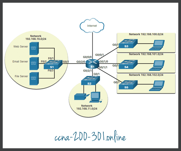
The figure displays a sample physical topology for a small sample network.
Physical Topology

The next figure displays a sample logical topology for the same network.
Logical Topology
WAN Topologies
The figures illustrate how WANs are commonly interconnected using three common physical WAN topologies.
Click each button for more information.
This is the simplest and most common WAN topology. It consists of a permanent link between two endpoints.

This is a WAN version of the star topology in which a central site interconnects branch sites through the use of point-to-point links. Branch sites cannot exchange data with other branch sites without going through the central site.
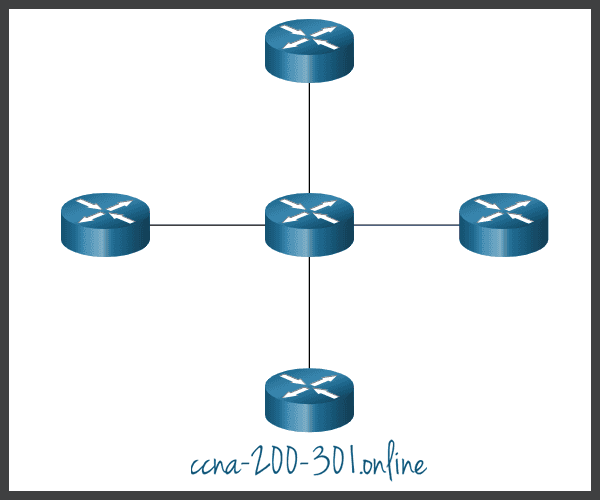
This topology provides high availability but requires that every end system is interconnected to every other system. Therefore, the administrative and physical costs can be significant. Each link is essentially a point-to-point link to the other node.

A hybrid is a variation or combination of any topologies. For example, a partial mesh is a hybrid topology in which some, but not all, end devices are interconnected.
Point-to-Point WAN Topology
Physical point-to-point topologies directly connect two nodes, as shown in the figure. In this arrangement, two nodes do not have to share the media with other hosts. Additionally, when using a serial communications protocol such as Point-to-Point Protocol (PPP), a node does not have to make any determination about whether an incoming frame is destined for it or another node. Therefore, the logical data link protocols can be very simple, as all frames on the media can only travel to or from the two nodes. The node places the frames on the media at one end and those frames are taken from the media by the node at the other end of the point-to-point circuit.
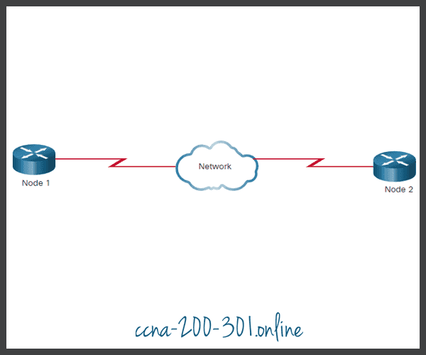
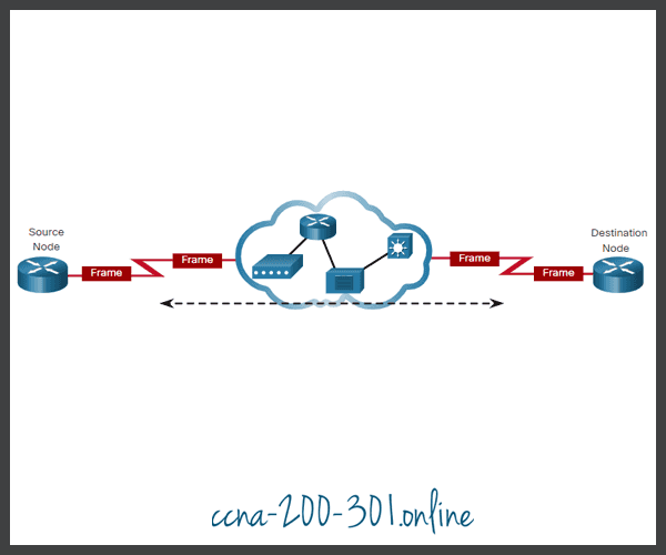
A source and destination node may be indirectly connected to each other over some geographical distance using multiple intermediary devices. However, the use of physical devices in the network does not affect the logical topology, as illustrated in the figure. In the figure, adding intermediary physical connections may not change the logical topology. The logical point-to-point connection is the same.
LAN Topologies
In multiaccess LANs, end devices (i.e., nodes) are interconnected using star or extended star topologies, as shown in the figure. In this type of topology, end devices are connected to a central intermediary device, in this case, an Ethernet switch. An extended star extends this topology by interconnecting multiple Ethernet switches. The star and extended topologies are easy to install, very scalable (easy to add and remove end devices), and easy to troubleshoot. Early star topologies interconnected end devices using Ethernet hubs.
At times there may be only two devices connected on the Ethernet LAN. An example is two interconnected routers. This would be an example of Ethernet used on a point-to-point topology.
Legacy LAN Topologies
Early Ethernet and legacy Token Ring LAN technologies included two other types of topologies:
- Bus – All end systems are chained to each other and terminated in some form on each end. Infrastructure devices such as switches are not required to interconnect the end devices. Legacy Ethernet networks were often bus topologies using coax cables because it was inexpensive and easy to set up.
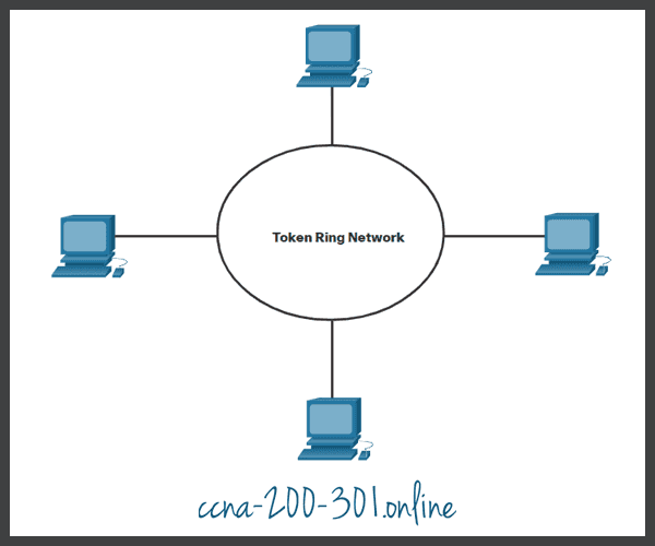
- Ring – End systems are connected to their respective neighbor forming a ring. The ring does not need to be terminated, unlike in the bus topology. Legacy Fiber Distributed Data Interface (FDDI) and Token Ring networks used ring topologies.
The figures illustrate how end devices are interconnected on LANs. It is common for a straight line in networking graphics to represent an Ethernet LAN including a simple star and an extended star.
Physical Topologies

Half and Full Duplex Communication
Understanding duplex communication is important when discussing LAN topologies because it refers to the direction of data transmission between two devices. There are two common modes of duplex.
Half-duplex communication
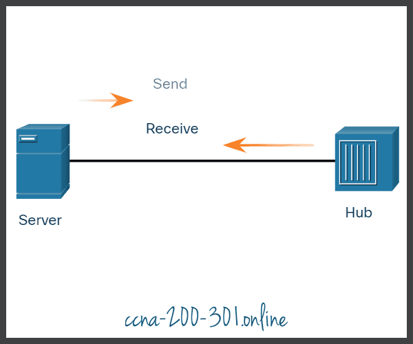
Both devices can transmit and receive on the media but cannot do so simultaneously. WLANs and legacy bus topologies with Ethernet hubs use the half-duplex mode. Half-duplex allows only one device to send or receive at a time on the shared medium. Click play in the figure to see the animation showing half-duplex communication.
Full-duplex communication
Both devices can simultaneously transmit and receive on the shared media. The data link layer assumes that the media is available for transmission for both nodes at any time. Ethernet switches operate in full-duplex mode by default, but they can operate in half-duplex if connecting to a device such as an Ethernet hub. Click play in the figure to see the animation showing full-duplex communication.
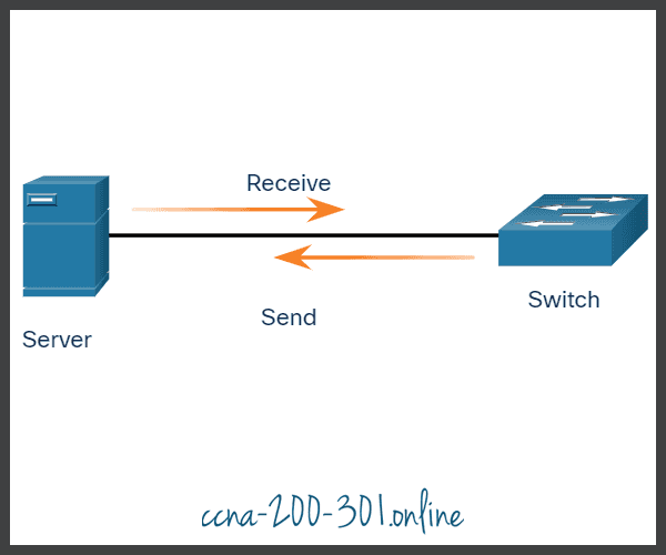
In summary, half-duplex communications restrict the exchange of data to one direction at a time. Full-duplex allows the sending and receiving of data to happen simultaneously.
It is important that two interconnected interfaces, such as a host NIC and an interface on an Ethernet switch, operate using the same duplex mode. Otherwise, there will be a duplex mismatch creating inefficiency and latency on the link.
Access Control Methods
Ethernet LANs and WLANs are examples of multiaccess networks. A multiaccess network is a network that can have two or more end devices attempting to access the network simultaneously.
Some multiaccess networks require rules to govern how devices share the physical media. There are two basic access control methods for shared media:
- Contention-based access
- Controlled access
Contention-based access
In contention-based multiaccess networks, all nodes are operating in half-duplex, competing for the use of the medium. However, only one device can send at a time. Therefore, there is a process if more than one device transmits at the same time. Examples of contention-based access methods include the following:
- Carrier sense multiple access with collision detection (CSMA/CD) used on legacy bus-topology Ethernet LANs
- Carrier sense multiple access with collision avoidance (CSMA/CA) used on Wireless LANs

Controlled access
In a controlled-based multiaccess network, each node has its own time to use the medium. These deterministic types of legacy networks are inefficient because a device must wait its turn to access the medium. Examples of multiaccess networks that use controlled access include the following:
- Legacy Token Ring
- Legacy ARCNET
Each node must wait for its turn to access the network medium.
Contention-Based Access – CSMA/CD
Examples of contention-based access networks include the following:
- Wireless LAN (uses CSMA/CA)
- Legacy bus-topology Ethernet LAN (uses CSMA/CD)
- Legacy Ethernet LAN using a hub (uses CSMA/CD)
These networks operate in half-duplex mode, meaning only one device can send or receive at a time. This requires a process to govern when a device can send and what happens when multiple devices send at the same time.
If two devices transmit at the same time, a collision will occur. For legacy Ethernet LANs, both devices will detect the collision on the network. This is the collision detection (CD) portion of CSMA/CD. The NIC compares data transmitted with data received, or by recognizing that the signal amplitude is higher than normal on the media. The data sent by both devices will be corrupted and will need to be resent.
Click each button for an image and description of the CSMA/CD process in legacy Ethernet LANs that use a hub.
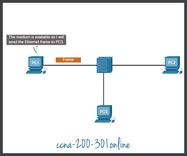
PC1 has an Ethernet frame to send to PC3. The PC1 NIC needs to determine if any device is transmitting on the medium. If it does not detect a carrier signal (in other words, it is not receiving transmissions from another device), it will assume the network is available to send.
The PC1 NIC sends the Ethernet Frame when the medium is available, as shown in the figure.
The Ethernet hub receives and sends the frame. An Ethernet hub is also known as a multiport repeater. Any bits received on an incoming port are regenerated and sent out all other ports, as shown in the figure.
If another device, such as PC2, wants to transmit, but is currently receiving a frame, it must wait until the channel is clear, as shown in the figure.

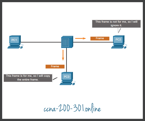
All devices attached to the hub will receive the frame. However, because the frame has a destination data link address for PC3, only that device will accept and copy in the entire frame. All other device NICs will ignore the frame, as shown in the figure.
Contention-Based Access – CSMA/CA
Another form of CSMA used by IEEE 802.11 WLANs is carrier sense multiple access/collision avoidance (CSMA/CA).
CMSA/CA uses a method similar to CSMA/CD to detect if the media is clear. CMSA/CA uses additional techniques. In wireless environments it may not be possible for a device to detect a collision. CMSA/CA does not detect collisions but attempts to avoid them by waiting before transmitting. Each device that transmits includes the time duration that it needs for the transmission. All other wireless devices receive this information and know how long the medium will be unavailable.
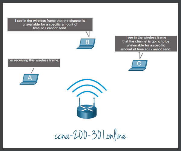
In the figure, if host A is receiving a wireless frame from the access point, hosts B, and C will also see the frame and how long the medium will be unavailable.
After a wireless device sends an 802.11 frame, the receiver returns an acknowledgment so that the sender knows the frame arrived.
Whether it is an Ethernet LAN using hubs, or a WLAN, contention-based systems do not scale well under heavy media use.
Ready to go! Keep visiting our networking course blog, give Like to our fanpage; and you will find more tools and concepts that will make you a networking professional.