Physical Layer Characteristics
Summary
This topic describe characteristics of the physical layer. Start learning CCNA 200-301 for free right now!!
Table of Contents
Physical Layer Standards
In the previous topic, you gained a high level overview of the physical layer and its place in a network. This topic dives a bit deeper into the specifics of the physical layer. This includes the components and the media used to build a network, as well as the standards that are required so that everything works together.
The protocols and operations of the upper OSI layers are performed using software designed by software engineers and computer scientists. The services and protocols in the TCP/IP suite are defined by the Internet Engineering Task Force (IETF).
The physical layer consists of electronic circuitry, media, and connectors developed by engineers. Therefore, it is appropriate that the standards governing this hardware are defined by the relevant electrical and communications engineering organizations.
There are many different international and national organizations, regulatory government organizations, and private companies involved in establishing and maintaining physical layer standards. For instance, the physical layer hardware, media, encoding, and signaling standards are defined and governed by these standards organizations:
- International Organization for Standardization (ISO)
- Telecommunications Industry Association/Electronic Industries Association (TIA/EIA)
- International Telecommunication Union (ITU)
- American National Standards Institute (ANSI)
- Institute of Electrical and Electronics Engineers (IEEE)
- National telecommunications regulatory authorities including the Federal Communication Commission (FCC) in the USA and the European Telecommunications Standards Institute (ETSI)
In addition to these, there are often regional cabling standards groups such as CSA (Canadian Standards Association), CENELEC (European Committee for Electrotechnical Standardization), and JSA/JIS (Japanese Standards Association), which develop local specifications.

Physical Components
The physical layer standards address three functional areas:
- Physical Components
- Encoding
- Signaling
Physical Components
The physical components are the electronic hardware devices, media, and other connectors that transmit the signals that represent the bits. Hardware components such as NICs, interfaces and connectors, cable materials, and cable designs are all specified in standards associated with the physical layer. The various ports and interfaces on a Cisco 1941 router are also examples of physical components with specific connectors and pinouts resulting from standards.
Encoding
Encoding or line encoding is a method of converting a stream of data bits into a predefined “code”. Codes are groupings of bits used to provide a predictable pattern that can be recognized by both the sender and the receiver. In other words, encoding is the method or pattern used to represent digital information. This is similar to how Morse code encodes a message using a series of dots and dashes.
For example, Manchester encoding represents a 0 bit by a high to low voltage transition, and a 1 bit is represented as a low to high voltage transition. An example of Manchester encoding is illustrated in the figure. The transition occurs at the middle of each bit period. This type of encoding is used in 10 Mbps Ethernet. Faster data rates require more complex encoding. Manchester encoding is used in older Ethernet standards such as 10BASE-T. Ethernet 100BASE-TX uses 4B/5B encoding and 1000BASE-T uses 8B/10B encoding.

The transition occurs at the middle of each bit period.
Signaling
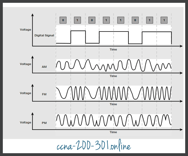
The physical layer must generate the electrical, optical, or wireless signals that represent the “1” and “0” on the media. The way that bits are represented is called the signaling method. The physical layer standards must define what type of signal represents a “1” and what type of signal represents a “0”. This can be as simple as a change in the level of an electrical signal or optical pulse. For example, a long pulse might represent a 1 whereas a short pulse might represent a 0.
This is similar to the signaling method used in Morse code, which may use a series of on-off tones, lights, or clicks to send text over telephone wires or between ships at sea.
The figures display signaling
Click each button for illustrations of signaling for copper cable, fiber-optic cable, and wireless media.
Electrical Signals Over Copper Cable

Light Pulses Over Fiber-Optic Cable

Microwave Signals Over Wireless
Bandwidth
Different physical media support the transfer of bits at different rates. Data transfer is usually discussed in terms of bandwidth. Bandwidth is the capacity at which a medium can carry data. Digital bandwidth measures the amount of data that can flow from one place to another in a given amount of time. Bandwidth is typically measured in kilobits per second (kbps), megabits per second (Mbps), or gigabits per second (Gbps). Bandwidth is sometimes thought of as the speed that bits travel, however this is not accurate. For example, in both 10Mbps and 100Mbps Ethernet, the bits are sent at the speed of electricity. The difference is the number of bits that are transmitted per second.
A combination of factors determines the practical bandwidth of a network:
- The properties of the physical media
- The technologies chosen for signaling and detecting network signals
Physical media properties, current technologies, and the laws of physics all play a role in determining the available bandwidth.
The table shows the commonly used units of measure for bandwidth.
| Unit of Bandwidth | Abbreviation | Equivalence |
|---|---|---|
| Bits per second | bps | 1 bps = fundamental unit of bandwidth |
| Kilobits per second | Kbps | 1 Kbps = 1,000 bps = 103 bps |
| Megabits per second | Mbps | 1 Mbps = 1,000,000 bps = 106 bps |
| Gigabits per second | Gbps | 1 Gbps = 1,000,000,000 bps = 109 bps |
| Terabits per second | Tbps | 1 Tbps = 1,000,000,000,000 bps = 1012 bps |
Bandwidth Terminology
Terms used to measure the quality of bandwidth include:
- Latency
- Throughput
- Goodput
Latency
Latency refers to the amount of time, including delays, for data to travel from one given point to another.
In an internetwork, or a network with multiple segments, throughput cannot be faster than the slowest link in the path from source to destination. Even if all, or most, of the segments have high bandwidth, it will only take one segment in the path with low throughput to create a bottleneck in the throughput of the entire network.
Throughput
Throughput is the measure of the transfer of bits across the media over a given period of time.
Due to a number of factors, throughput usually does not match the specified bandwidth in physical layer implementations. Throughput is usually lower than the bandwidth. There are many factors that influence throughput:
- The amount of traffic
- The type of traffic
- The latency created by the number of network devices encountered between source and destination
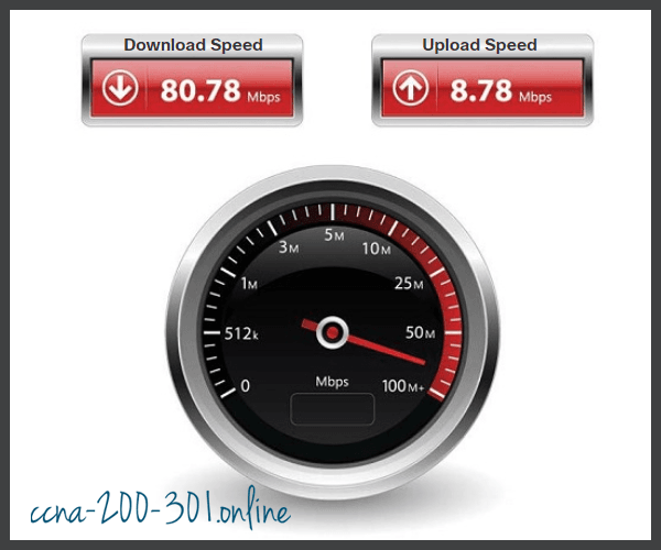
There are many online speed tests that can reveal the throughput of an internet connection. The figure provides sample results from a speed test.
Goodput
There is a third measurement to assess the transfer of usable data; it is known as goodput. Goodput is the measure of usable data transferred over a given period of time. Goodput is throughput minus traffic overhead for establishing sessions, acknowledgments, encapsulation, and retransmitted bits. Goodput is always lower than throughput, which is generally lower than the bandwidth.
Ready to go! Keep visiting our networking course blog, give Like to our fanpage; and you will find more tools and concepts that will make you a networking professional.