Introduction to Routing
Summary
This topic explain the function of fields in the routing table of a router. Start learning CCNA 200-301 for free right now!!
Table of Contents
Router Packet Forwarding Decision
The previous topic discussed host routing tables. Most networks also contain routers, which are intermediary devices. Routers also contain routing tables. This topic covers router operations at the network layer. When a host sends a packet to another host, it consults its routing table to determine where to send the packet. If the destination host is on a remote network, the packet is forwarded to the default gateway, which is usually the local router.
What happens when a packet arrives on a router interface?
The router examines the destination IP address of the packet and searches its routing table to determine where to forward the packet. The routing table contains a list of all known network addresses (prefixes) and where to forward the packet. These entries are known as route entries or routes. The router will forward the packet using the best (longest) matching route entry.

- Packet arrives on the Gigabit Ethernet 0/0/0 interface of router R1. R1 de-encapsulates the Layer 2 Ethernet header and trailer.
- Router R1 examines the destination IPv4 address of the packet and searches for the best match in its IPv4 routing table. The route entry indicates that this packet is to be forwarded to router R2.
- Router R1 encapsulates the packet into a new Ethernet header and trailer, and forwards the packet to the next hop router R2.
The following table shows the pertinent information from the R1 routing table.
R1 Routing Table
| Route | Next Hop or Exit Interface |
|---|---|
| 192.168.10.0 /24 | G0/0/0 |
| 209.165.200.224/30 | G0/0/1 |
| 10.1.1.0/24 | via R2 |
| Default Route 0.0.0.0/0 | via R2 |
IP Router Routing Table
The routing table of the router contains network route entries listing all the possible known network destinations.
The routing table stores three types of route entries:
- Directly-connected networks – These network route entries are active router interfaces. Routers add a directly connected route when an interface is configured with an IP address and is activated. Each router interface is connected to a different network segment. In the figure, the directly-connected networks in the R1 IPv4 routing table would be 192.168.10.0/24 and 209.165.200.224/30.
- Remote networks – These network route entries are connected to other routers. Routers learn about remote networks either by being explicitly configured by an administrator or by exchanging route information using a dynamic routing protocol. In the figure, the remote network in the R1 IPv4 routing table would be 10.1.1.0/24.
- Default route – Like a host, most routers also include a default route entry, a gateway of last resort. The default route is used when there is no better (longer) match in the IP routing table. In the figure, the R1 IPv4 routing table would most likely include a default route to forward all packets to router R2.
The figure identifies the directly connected and remote networks of router R1.
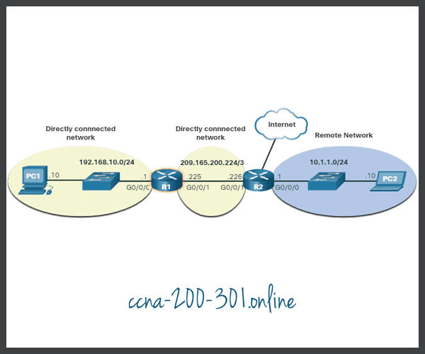
R1 has two directly connect networks:
- 192.168.10.0/24
- 209.165.200.224/30
R1 also has remote networks (i.e. 10.1.1.0/24 and the internet) that it can learn about.
A router can learn about remote networks in one of two ways:
- Manually – Remote networks are manually entered into the route table using static routes.
- Dynamically – Remote routes are automatically learned using a dynamic routing protocol.
Static Routing
Static routes are route entries that are manually configured. The figure shows an example of a static route that was manually configured on router R1. The static route includes the remote network address and the IP address of the next hop router.

R1 is manually configured with a static route to reach the 10.1.1.0/24 network. If this path changes, R1 will require a new static route.
If there is a change in the network topology, the static route is not automatically updated and must be manually reconfigured. For example, in the figure R1 has a static route to reach the 10.1.1.0/24 network via R2. If that path is no longer available, R1 would need to be reconfigured with a new static route to the 10.1.1.0/24 network via R3. Router R3 would therefore need to have a route entry in its routing table to send packets destined for 10.1.1.0/24 to R2.

If the route from R1 via R2 is no longer available, a new static route via R3 would need to be configured. A static route does not automatically adjust for topology changes.
Static routing has the following characteristics:
- A static route must be configured manually.
- The administrator needs to reconfigure a static route if there is a change in the topology and the static route is no longer viable.
- A static route is appropriate for a small network and when there are few or no redundant links.
- A static route is commonly used with a dynamic routing protocol for configuring a default route.
Dynamic Routing
A dynamic routing protocol allows the routers to automatically learn about remote networks, including a default route, from other routers. Routers that use dynamic routing protocols automatically share routing information with other routers and compensate for any topology changes without involving the network administrator. If there is a change in the network topology, routers share this information using the dynamic routing protocol and automatically update their routing tables.
Dynamic routing protocols include OSPF and Enhanced Interior Gateway Routing Protocol (EIGRP). The figure shows an example of routers R1 and R2 automatically sharing network information using the routing protocol OSPF.

- R1 is using the routing protocol OSPF to let R2 know about the 192.168.10.0/24 network.
- R2 is using the routing protocol OSPF to let R1 know about the 10.1.1.0/24 network.
Basic configuration only requires the network administrator to enable the directly connected networks within the dynamic routing protocol. The dynamic routing protocol will automatically do as follows:
- Discover remote networks
- Maintain up-to-date routing information
- Choose the best path to destination networks
- Attempt to find a new best path if the current path is no longer available
When a router is manually configured with a static route or learns about a remote network dynamically using a dynamic routing protocol, the remote network address and next hop address are entered into the IP routing table. As shown in the figure, if there is a change in the network topology, the routers will automatically adjust and attempt to find a new best path.

R1, R2, and R3 are using the dynamic routing protocol OSPF. If there is a network topology change, they can automatically adjust to find a new best path.
Video- IPv4 Router Routing Tables
Unlike a host computer routing table, there are no column headings identifying the information contained in the routing table of a router. It is important to learn the meaning of the different items included in each entry of the routing table.
Click Play in the figure to view an introduction to the IPv4 routing table.
Introduction to an IPv4 Routing Table
Notice in the figure that R2 is connected to the internet. Therefore, the administrator configured R1 with a default static route sending packets to R2 when there is no specific entry in the routing table that matches the destination IP address. R1 and R2 are also using OSPF routing to advertise directly connected networks.

R1# show ip route
Codes: L - local, C - connected, S - static, R - RIP, M - mobile, B - BGP
D - EIGRP, EX - EIGRP external, O - OSPF, IA - OSPF inter area
N1 - OSPF NSSA external type 1, N2 - OSPF NSSA external type 2
E1 - OSPF external type 1, E2 - OSPF external type 2
i - IS-IS, su - IS-IS summary, L1 - IS-IS level-1, L2 - IS-IS level-2
ia - IS-IS inter area, * - candidate default, U - per-user static route
o - ODR, P - periodic downloaded static route, H - NHRP, l - LISP
a - application route
+ - replicated route, % - next hop override, p - overrides from PfR
Gateway of last resort is 209.165.200.226 to network 0.0.0.0
S* 0.0.0.0/0 [1/0] via 209.165.200.226, GigabitEthernet0/0/1
10.0.0.0/24 is subnetted, 1 subnets
O 10.1.1.0 [110/2] via 209.165.200.226, 00:02:45, GigabitEthernet0/0/1
192.168.10.0/24 is variably subnetted, 2 subnets, 2 masks
C 192.168.10.0/24 is directly connected, GigabitEthernet0/0/0
L 192.168.10.1/32 is directly connected, GigabitEthernet0/0/0
209.165.200.0/24 is variably subnetted, 2 subnets, 2 masks
C 209.165.200.224/30 is directly connected, GigabitEthernet0/0/1
L 209.165.200.225/32 is directly connected, GigabitEthernet0/0/1
R1#
The show ip route privileged EXEC mode command is used to view the IPv4 routing table on a Cisco IOS router. The example shows the IPv4 routing table of router R1. At the beginning of each routing table entry is a code that is used to identify the type of route or how the route was learned. Common route sources (codes) include these:
- L – Directly connected local interface IP address
- C – Directly connected network
- S – Static route was manually configured by an administrator
- O – OSPF
- D – EIGRP
The routing table displays all of the known IPv4 destination routes for R1.
A directly connected route is automatically created when a router interface is configured with IP address information and is activated. The router adds two route entries with the codes C (i.e., the connected network) and L (i.e., the local interface IP address of the connected network). The route entries also identify the exit interface to use to reach the network. The two directly connected networks in this example are 192.168.10.0/24 and 209.165.200.224/30.
Routers R1 and R2 are also using the OSPF dynamic routing protocol to exchange router information. In the example routing table, R1 has a route entry for the 10.1.1.0/24 network that it learned dynamically from router R2 via the OSPF routing protocol.
A default route has a network address of all zeroes. For example, the IPv4 network address is 0.0.0.0. A static route entry in the routing table begins with a code of S*, as highlighted in the example.
Ready to go! Keep visiting our networking course blog, give Like to our fanpage; and you will find more tools and concepts that will make you a networking professional.