NTP
Summary
This topic implement NTP between an NTP client and NTP server. Start learning CCNA 200-301 for free right now!!
Table of Contents
Time and Calendar Services
Before you get really deep into network management, the one thing that will help keep you on track is ensuring that all of your components are set to the same time and date.
The software clock on a router or switch starts when the system boots. It is the primary source of time for the system. It is important to synchronize the time across all devices on the network because all aspects of managing, securing, troubleshooting, and planning networks require accurate timestamping. When the time is not synchronized between devices, it will be impossible to determine the order of the events and the cause of an event.
Typically, the date and time settings on a router or switch can be set by using one of two methods You can manually configure the date and time, as shown in the example, or configure the Network Time Protocol (NTP).
R1# clock set 20:36:00 nov 15 2019
R1#
*Nov 15 20:36:00.000: %SYS-6-CLOCKUPDATE: System clock has been
updated from 21:32:31 UTC Fri Nov 15 2019 to 20:36:00 UTC Fri Nov 15
2019, configured from console by console.
As a network grows, it becomes difficult to ensure that all infrastructure devices are operating with synchronized time. Even in a smaller network environment, the manual method is not ideal. If a router reboots, how will it get an accurate date and timestamp?
A better solution is to configure the NTP on the network. This protocol allows routers on the network to synchronize their time settings with an NTP server. A group of NTP clients that obtain time and date information from a single source have more consistent time settings. When NTP is implemented in the network, it can be set up to synchronize to a private master clock, or it can synchronize to a publicly available NTP server on the internet.
NTP uses UDP port 123 and is documented in RFC 1305.
NTP Operation
NTP networks use a hierarchical system of time sources. Each level in this hierarchical system is called a stratum. The stratum level is defined as the number of hop counts from the authoritative source. The synchronized time is distributed across the network by using NTP. The figure displays a sample NTP network.
NTP servers are arranged in three levels showing the three strata. Stratum 1 is connected to Stratum 0 clocks.

Stratum 0
An NTP network gets the time from authoritative time sources. Stratum 0 devices such as atomic and GPS clocks are the most accurate authoritative time sources. Specifically, stratum 0 devices are non-network high-precision timekeeping devices assumed to be accurate and with little or no delay associated with them. In the figure, they are represented by the clock icon.
Stratum 1
The stratum 1 devices are network devices that are directly connected to the authoritative time sources. They function as the primary network time standard to stratum 2 devices using NTP.
Stratum 2 and Lower
The stratum 2 servers are connected to stratum 1 devices through network connections. Stratum 2 devices, such as NTP clients, synchronize their time by using the NTP packets from stratum 1 servers. They could also act as servers for stratum 3 devices.
Smaller stratum numbers indicate that the server is closer to the authorized time source than larger stratum numbers. The larger the stratum number, the lower the stratum level. The max hop count is 15. Stratum 16, the lowest stratum level, indicates that a device is unsynchronized. Time servers on the same stratum level can be configured to act as a peer with other time servers on the same stratum level for backup or verification of time.
Configure and Verify NTP
The figure shows the topology used to demonstrate NTP configuration and verification.
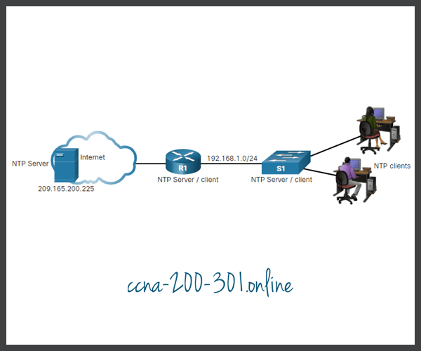
Before NTP is configured on the network, the show clock command displays the current time on the software clock, as shown in the example. With the detail option, notice that the time source is user configuration. That means the time was manually configured with the clock command.
R1# show clock detail
20:55:10.207 UTC Fri Nov 15 2019
Time source is user configuration
The ntp server ip-address command is issued in global configuration mode to configure 209.165.200.225 as the NTP server for R1. To verify the time source is set to NTP, use the show clock detail command. Notice that now the time source is NTP.
R1(config)# ntp server 209.165.200.225
R1(config)# end
R1# show clock detail
21:01:34.563 UTC Fri Nov 15 2019
Time source is NTP
In the next example, the show ntp associations and show ntp status commands are used to verify that R1 is synchronized with the NTP server at 209.165.200.225. Notice that R1 is synchronized with a stratum 1 NTP server at 209.165.200.225, which is synchronized with a GPS clock. The show ntp status command displays that R1 is now a stratum 2 device that is synchronized with the NTP server at 209.165.220.225.
R1# show ntp associations

  address         ref clock       st   when   poll reach  delay  offset   disp
*~209.165.200.225 .GPS.           1     61     64   377  0.481   7.480  4.261
 * sys.peer, # selected, + candidate, - outlyer, x falseticker, ~ configured

R1# show ntp status
Clock is synchronized, stratum 2, reference is 209.165.200.225
nominal freq is 250.0000 Hz, actual freq is 249.9995 Hz, precision is 2**19
ntp uptime is 589900 (1/100 of seconds), resolution is 4016
reference time is DA088DD3.C4E659D3 (13:21:23.769 PST Fri Nov 15 2019)
clock offset is 7.0883 msec, root delay is 99.77 msec
root dispersion is 13.43 msec, peer dispersion is 2.48 msec
loopfilter state is 'CTRL' (Normal Controlled Loop), drift is 0.000001803 s/s
system poll interval is 64, last update was 169 sec ago.
Next, the clock on S1 is configured to synchronize to R1 with the ntp server command and then the configuration is verified with the show ntp associations command, as displayed.
S1(config)# ntp server 192.168.1.1
S1(config)# end
S1# show ntp associations

  address         ref clock       st   when   poll reach  delay  offset   disp
*~192.168.1.1     209.165.200.225  2     12     64   377  1.066  13.616  3.840
 * sys.peer, # selected, + candidate, - outlyer, x falseticker, ~ configured
Output from the show ntp associations command verifies that the clock on S1 is now synchronized with R1 at 192.168.1.1 via NTP. R1 is a stratum 2 device and NTP server to S1. Now S1 is a stratum 3 device that can provide NTP service to other devices in the network, such as end devices.
S1# show ntp status
Clock is synchronized, stratum 3, reference is 192.168.1.1
nominal freq is 119.2092 Hz, actual freq is 119.2088 Hz, precision is 2**17
reference time is DA08904B.3269C655 (13:31:55.196 PST Tue Nov 15 2019)
clock offset is 18.7764 msec, root delay is 102.42 msec
root dispersion is 38.03 msec, peer dispersion is 3.74 msec
loopfilter state is 'CTRL' (Normal Controlled Loop), drift is 0.000003925 s/s
system poll interval is 128, last update was 178 sec ago.
Packet Tracer – Configure and Verify NTP
NTP synchronizes the time of day among a set of distributed time servers and clients. While there are a number of applications that require synchronized time, this lab will focus on the need to correlate events when listed in the system logs and other time-specific events from multiple network devices.
Ready to go! Keep visiting our networking course blog, give Like to our fanpage; and you will find more tools and concepts that will make you a networking professional.