Data Access
Summary
This topic explain how local hosts access local resources on a network. Start learning CCNA 200-301 for free right now!!
Table of Contents
Addresses
As you just learned, it is necessary to segment messages in a network. But those segmented messages will not go anywhere if they are not addressed properly. This topic gives an overview of network addresses. You will also get the chance to use the Wireshark tool, which will help you to ‘view’ network traffic.
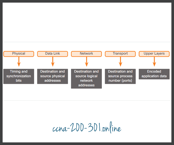
The network and data link layers are responsible for delivering the data from the source device to the destination device. As shown in the figure, protocols at both layers contain a source and destination address, but their addresses have different purposes:
- Network layer source and destination addresses – Responsible for delivering the IP packet from the original source to the final destination, which may be on the same network or a remote network.
- Data link layer source and destination addresses – Responsible for delivering the data link frame from one network interface card (NIC) to another NIC on the same network.
Layer 3 Logical Address
An IP address is the network layer, or Layer 3, logical address used to deliver the IP packet from the original source to the final destination, as shown in the figure.

The IP packet contains two IP addresses:
- Source IP address – The IP address of the sending device, which is the original source of the packet.
- Destination IP address – The IP address of the receiving device, which is the final destination of the packet.
The IP addresses indicate the original source IP address and final destination IP address. This is true whether the source and destination are on the same IP network or different IP networks.
An IP address contains two parts:
- Network portion (IPv4) or Prefix (IPv6) – The left-most part of the address that indicates the network in which the IP address is a member. All devices on the same network will have the same network portion of the address.
- Host portion (IPv4) or Interface ID (IPv6) – The remaining part of the address that identifies a specific device on the network. This portion is unique for each device or interface on the network.
Devices on the Same Network
In this example we have a client computer, PC1, communicating with an FTP server on the same IP network.
- Source IPv4 address – The IPv4 address of the sending device, the client computer PC1: 192.168.1.110.
- Destination IPv4 address – The IPv4 address of the receiving device, FTP server: 192.168.1.9.
Notice in the figure that the network portion of both the source IPv4 address and destination IPv4 address are on the same network. Notice in the figure that the network portion of the source IPv4 address and the network portion of the destination IPv4 address are the same and therefore; the source and destination are on the same network.

Role of the Data Link Layer Addresses: Same IP Network
When the sender and receiver of the IP packet are on the same network, the data link frame is sent directly to the receiving device. On an Ethernet network, the data link addresses are known as Ethernet Media Access Control (MAC) addresses, as highlighted in the figure.

MAC addresses are physically embedded on the Ethernet NIC.
- Source MAC address – This is the data link address, or the Ethernet MAC address, of the device that sends the data link frame with the encapsulated IP packet. The MAC address of the Ethernet NIC of PC1 is AA-AA-AA-AA-AA-AA, written in hexadecimal notation.
- Destination MAC address – When the receiving device is on the same network as the sending device, this is the data link address of the receiving device. In this example, the destination MAC address is the MAC address of the FTP server: CC-CC-CC-CC-CC-CC, written in hexadecimal notation.
The frame with the encapsulated IP packet can now be transmitted from PC1 directly to the FTP server.
Devices on a Remote Network
But what are the roles of the network layer address and the data link layer address when a device is communicating with a device on a remote network? In this example we have a client computer, PC1, communicating with a server, named Web Server, on a different IP network.
Role of the Network Layer Addresses
When the sender of the packet is on a different network from the receiver, the source and destination IP addresses will represent hosts on different networks. This will be indicated by the network portion of the IP address of the destination host.
- Source IPv4 address – The IPv4 address of the sending device, the client computer PC1: 192.168.1.110.
- Destination IPv4 address – The IPv4 address of the receiving device, the server, Web Server: 172.16.1.99.
Notice in the figure that the network portion of the source IPv4 address and destination IPv4 address are on different networks.

Role of the Data Link Layer Addresses: Different IP Networks
When the sender and receiver of the IP packet are on different networks, the Ethernet data link frame cannot be sent directly to the destination host because the host is not directly reachable in the network of the sender. The Ethernet frame must be sent to another device known as the router or default gateway. In our example, the default gateway is R1. R1 has an Ethernet data link address that is on the same network as PC1. This allows PC1 to reach the router directly.
- Source MAC address – The Ethernet MAC address of the sending device, PC1. The MAC address of the Ethernet interface of PC1 is AA-AA-AA-AA-AA-AA.
- Destination MAC address – When the receiving device, the destination IP address, is on a different network from the sending device, the sending device uses the Ethernet MAC address of the default gateway or router. In this example, the destination MAC address is the MAC address of the R1 Ethernet interface, 11-11-11-11-11-11. This is the interface that is attached to the same network as PC1, as shown in the figure.
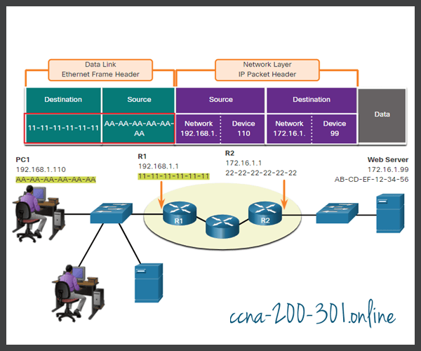
The Ethernet frame with the encapsulated IP packet can now be transmitted to R1. R1 forwards the packet to the destination, Web Server. This may mean that R1 forwards the packet to another router or directly to Web Server if the destination is on a network connected to R1.
It is important that the IP address of the default gateway be configured on each host on the local network. All packets to a destination on remote networks are sent to the default gateway. Ethernet MAC addresses and the default gateway are discussed in more detail in other modules.
Data Link Addresses
The data link Layer 2 physical address has a different role. The purpose of the data link address is to deliver the data link frame from one network interface to another network interface on the same network.
Before an IP packet can be sent over a wired or wireless network, it must be encapsulated in a data link frame, so it can be transmitted over the physical medium.
Click each button to view an illustration of how the data link layer addresses change at every hop from source to destination
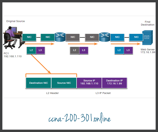
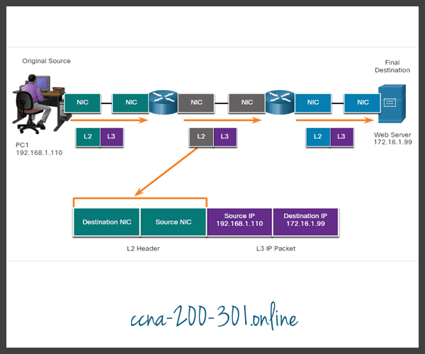

As the IP packet travels from host-to-router, router-to-router, and finally router-to-host, at each point along the way the IP packet is encapsulated in a new data link frame. Each data link frame contains the source data link address of the NIC card sending the frame, and the destination data link address of the NIC card receiving the frame.
The Layer 2, data link protocol is only used to deliver the packet from NIC-to-NIC on the same network. The router removes the Layer 2 information as it is received on one NIC and adds new data link information before forwarding out the exit NIC on its way towards the final destination.
The IP packet is encapsulated in a data link frame that contains the following data link information:
- Source data link address – The physical address of the NIC that is sending the data link frame.
- Destination data link address – The physical address of the NIC that is receiving the data link frame. This address is either the next hop router or the address of the final destination device.
Lab – Install Wireshark
Wireshark is a software protocol analyzer, or “packet sniffer” application, used for network troubleshooting, analysis, software and protocol development, and education. Wireshark is used throughout the course to demonstrate network concepts. In this lab, you will download and install Wireshark.
Lab – Use Wireshark to View Network Traffic
In this lab, you will use Wireshark to capture and analyze traffic.
Ready to go! Keep visiting our networking course blog, give Like to our fanpage; and you will find more tools and concepts that will make you a networking professional.